
Image vibration-compensating apparatus and method thereof

a technology of vibration compensation and image frame, which is applied in the field of image capture apparatus, can solve the problems of increased cost, inability to meet user expectations, and increased volume and weight of digital image capture apparatus, and achieve the effect of reducing calculation requirements and reasonable prices

Inactive Publication Date: 2010-12-21
NOVATEK MICROELECTRONICS CORP
View PDF20 Cites 11 Cited by
  • Summary
  • Abstract
  • Description
  • Claims
  • Application Information

AI Technical Summary

Benefits of technology

The present invention provides an image vibration-compensating apparatus and method for image-capturing apparatus such as digital still cameras (DSC) and digital video recorders (DVR). The apparatus and method use an adaptive edge extractor, sub-region movement detector, frame motion calculator, and correcting vector generator to compensate for image vibration. The apparatus and method can simplify image data and reduce calculation requirements, making it more affordable for image-capturing apparatus. Additionally, the apparatus and method can prevent visual discomfort caused by fast jitter of the image frame and stabilize the image frame. The technical effects of the invention include improved image quality, reduced computational requirements, and improved user experience.

Problems solved by technology

However, when the digital image-capturing apparatus becomes light and thin, an image vibration may be resulted from the vibration of the digital image-capturing apparatus while capturing an image and thus the photo image frame cannot meet the user's expectation.
However, the gyroscope detector and the gimbals mechanism have the shortcomings of great weight, large volume, high price, etc., such that the volume and weight of the digital image-capturing apparatus cannot be reduced and the cost is increased.
However, the manner of determining the best bit plane by referencing the amount of lumens and the bit conversion rate of each bit plane is not perfect.

Method used


Image

  • Image vibration-compensating apparatus and method thereof
  • Image vibration-compensating apparatus and method thereof
  • Image vibration-compensating apparatus and method thereof

Examples


Embodiment Construction

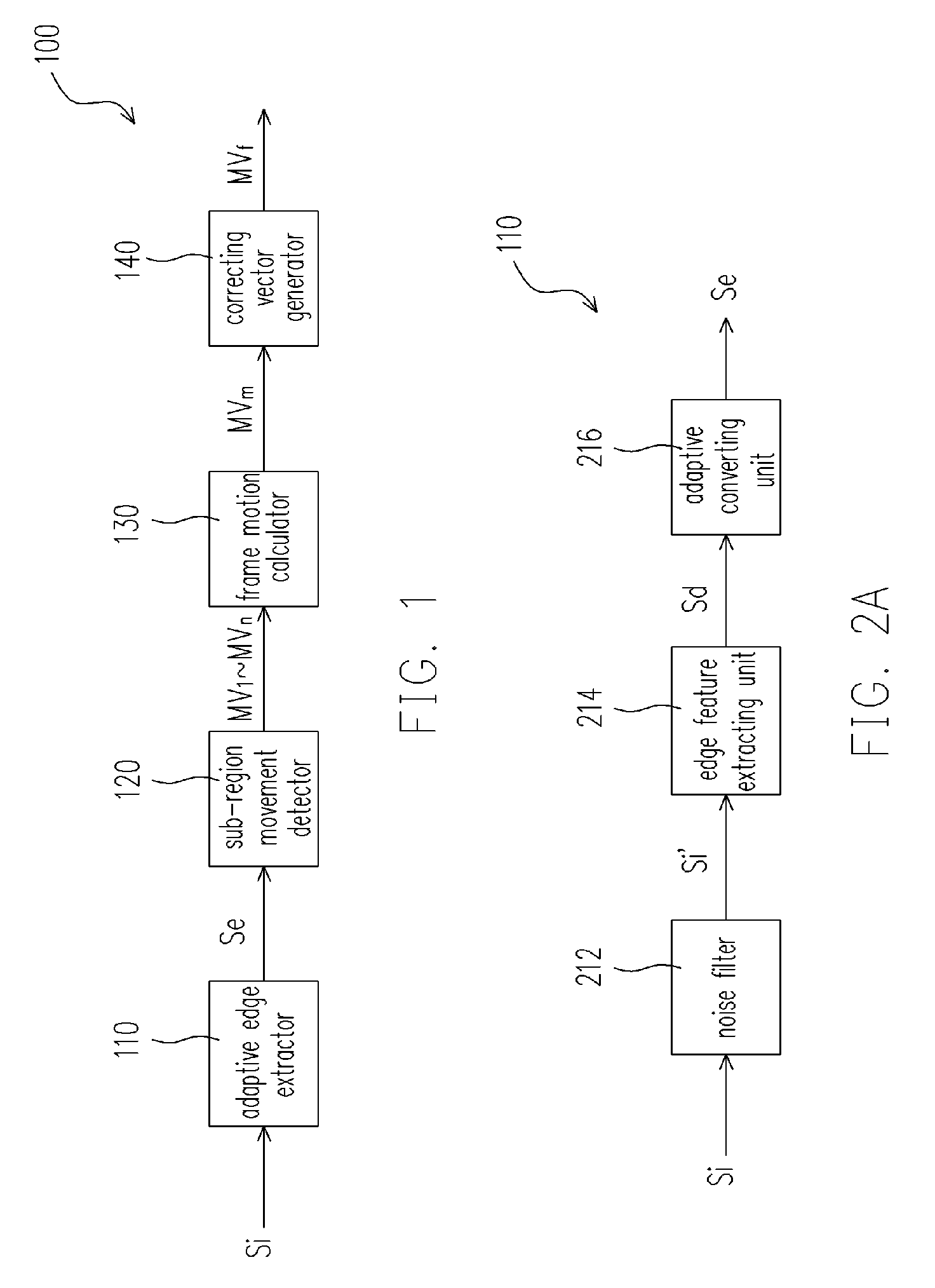
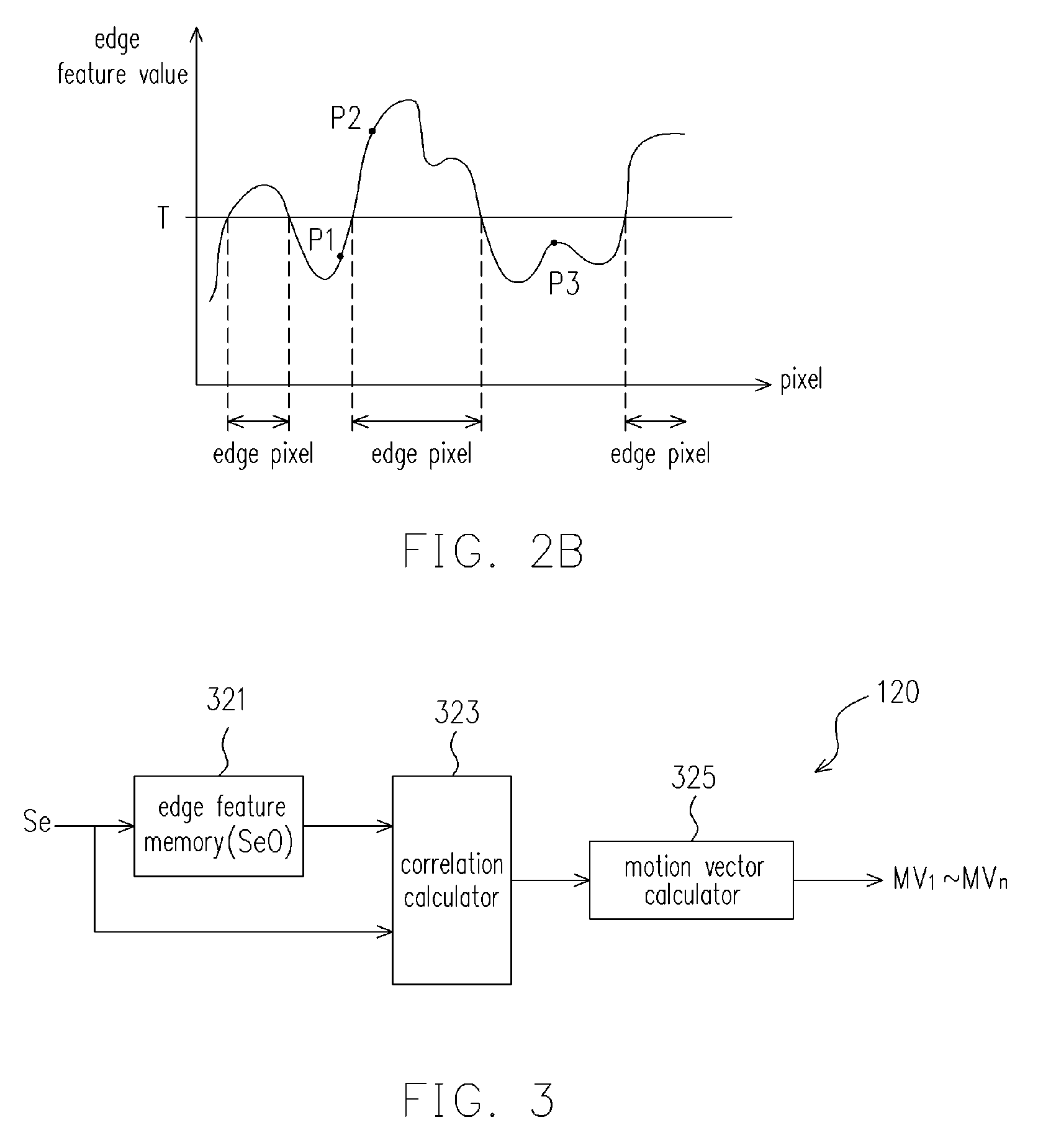
[0033]FIG. 1 is a structural block diagram of an image vibration-compensating apparatus according to one embodiment of the present invention. Referring to FIG. 1, in an embodiment, an image vibration-compensating apparatus 100 is used for enabling an image-capturing apparatus such as a digital still camera (DSC) or a digital video recorder (DVR) to compensate the image frame vibration of the captured image due to the vibration. The image vibration-compensating apparatus 100 comprises an adaptive edge extractor 110, a sub-region movement detector 120, a frame motion calculator 130, and a correcting vector generator 140. The adaptive edge extractor 110 outputs an edge feature signal Se according to the image signal Si of the image frame captured by the image-capturing apparatus. The sub-region movement detector 120 is electrically connected to the adaptive edge extractor 110 for outputting multiple first motion vectors MV1˜MVn according to the edge feature signal Se, where n is an int...


PUM


Abstract

An image vibration-compensating apparatus and a method thereof are provided. The apparatus and the method are applied in an image-capturing apparatus, such as a digital still camera (DSC) or digital video recorder (DVR), for compensating image vibration when capturing an image. The image vibration-compensating apparatus comprises an adaptive edge extractor, a sub-region movement detector, a frame motion calculator, and a correcting vector generator. The image vibration-compensating apparatus analyses the difference between the current image and the previous image, and outputs the correcting motion vector to achieve the function of image vibration-compensation. In the image vibration-compensating method, an accumulate compensation mode is used to prevent fast motion of an image frame which will cause discomfort of the user's eyes when a relatively large image vibration occurs in a short period.

Description

CROSS-REFERENCE TO RELATED APPLICATION[0001]This application claims the priority benefit of Taiwan application serial no. 94143839, filed on Dec. 12, 2005. All disclosure of the Taiwan application is incorporated herein by reference.BACKGROUND OF THE INVENTION[0002]1. Field of Invention[0003]The present invention relates to an image-capturing apparatus, and more particularly, to an image vibration-compensating apparatus and a method thereof applied in the image-capturing apparatus.[0004]2. Description of Related Art[0005]The digital image-capturing apparatus has replaced the conventional mechanical image-capturing apparatus. Many control and calculation mechanisms used in the digital image-capturing apparatus have replaced the conventional mechanical camera components. Therefore, light, thin, short, and small digital image-capturing apparatuses widely accepted by consumers are commercially available. However, when the digital image-capturing apparatus becomes light and thin, an imag...

Claims


Application Information

Patent Timeline
Patent Type & Authority Patents(United States)
IPC IPC(8): H04N5/228H04N23/40
CPCH04N5/144H04N5/23248H04N5/23254H04N5/23264H04N23/682H04N23/6811H04N23/68
Inventor YU, SHU-HAN
Owner NOVATEK MICROELECTRONICS CORP
Learn More