Furnace

a furnace and gas technology, applied in the field of furnaces, can solve the problems of large swings in air temperature, increased co emissions, and general limitations of furnaces and burners of this type, and achieve the effects of increasing co emissions, increasing flame stability, and high port loading

Active Publication Date: 2010-12-14
BECKETT GAS
View PDF6 Cites 10 Cited by
  • Summary
  • Abstract
  • Description
  • Claims
  • Application Information

AI Technical Summary

Benefits of technology

[0010]In accordance with a feature of the invention, the baffle member is offset within the collector chamber so that the size of the collector chamber sections compensates for differences in mass flow density of the gases flowing out of the heat exchange tubes during furnace operation. When only the first group of burners is being fired, ambient, secondary air is being drawn through the heat exchange tubes associated with the other group of burners. Ambient air has a mass flow density that is greater than flue gases that are flowing through the heat exchange tubes associated with the first group of burners. Offsetting of the baffle within the collector chamber compensates for the differences in mass flow density of the ambient air and flue gases being conveyed to respective collector chamber sections.
[0011]In accordance with another feature of the invention, a shoot-through plate including openings aligned with the burner and the associated heat exchange tube inlet is spaced from the tube inlet so as to provide a secondary air path that is radial or offset with respect to an axis of the burner. In the past, secondary air for combustion flowed along the burner body along a path that is generally parallel to the axis of the burner. With the disclosed invention, secondary air travels in a substantially orthogonal path with respect to the burner body and results in increased flame stability. In addition, the burners can be operated at a high port loading without substantially increasing CO emissions or causing flame instability.
[0012]In the preferred and illustrated embodiment, a secondary air blocking plate extends from the shoot-through plate to a bracket that supports a burner in its operative position. This blocking plate restricts the flow of secondary air along the body of the burner and also aids in flame stability and reduction in CO emissions.
[0014]In accordance with still another feature of the invention, multiple furnace modules may be mounted in a single cabinet or duct structure to provide an effective turndown ratio for the overall heating apparatus that is substantially greater than 8:1. For example, two furnace modules may be mounted in the duct where one module is constructed in accordance with the preferred embodiment of the invention (and is capable of a 8:1 turndown ratio) whereas the other furnace module is of a standard configuration and can be operated at a 2:1 turndown ratio. With this combination of furnace modules, an effective turndown ratio of 32:1 can be achieved.

Problems solved by technology

If the furnace is only capable of operating at one BTU level, large swings in air temperature can result due to the on / off cycling of the furnace.
It has been found that furnaces and burners of this type are generally limited to a maximum 2:1 turndown ratio, i.e., the furnace can operate at either 50% or full output.
Generally, as the furnace output is reduced, CO emissions increase and flame instability may also result.
Attempts have been made to provide duct-type furnaces capable of operating at less than 50% of maximum output, but these attempts have not been totally successful.

Method used


Image

  • Furnace
  • Furnace
  • Furnace

Examples


Embodiment Construction

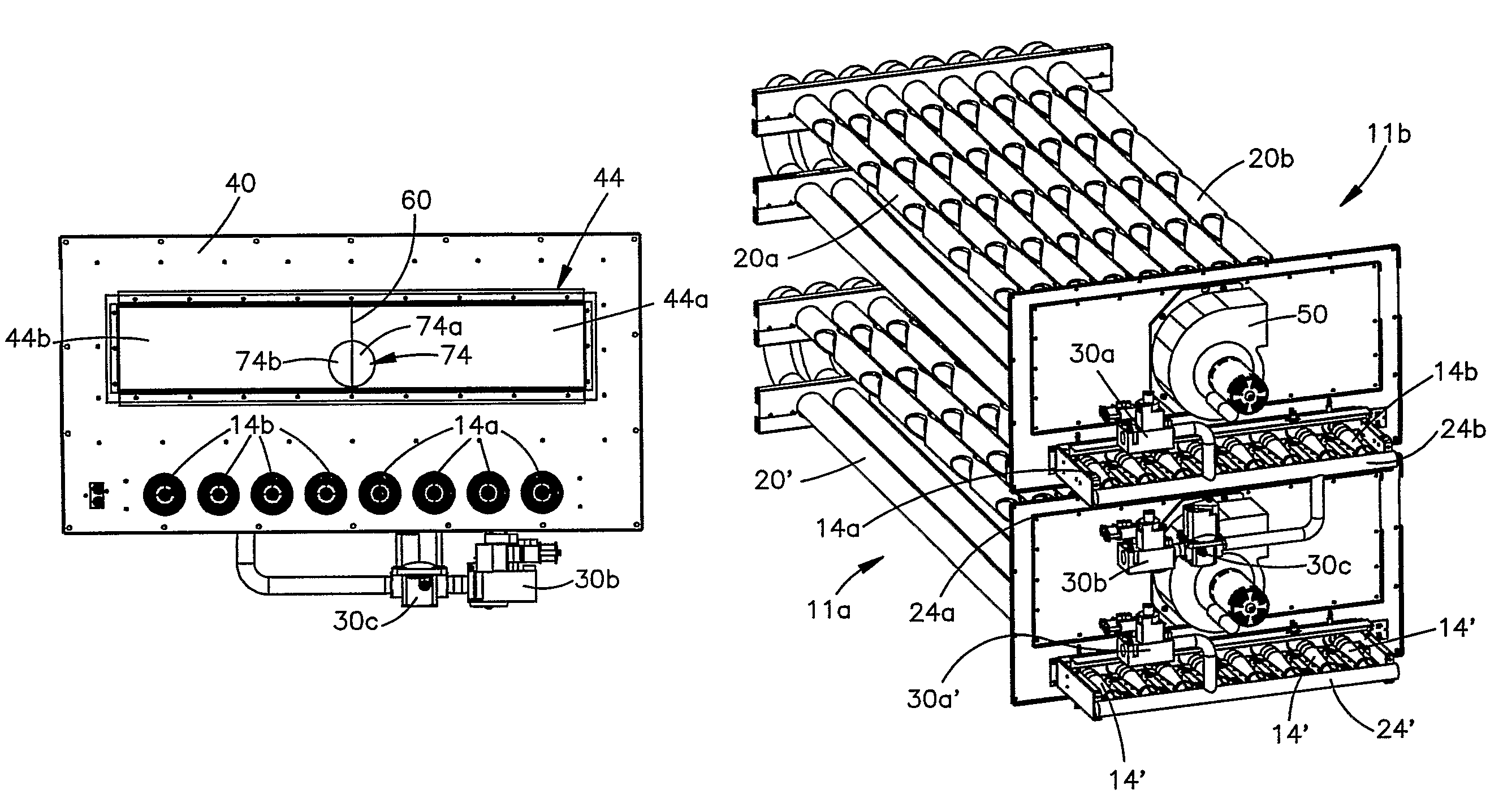
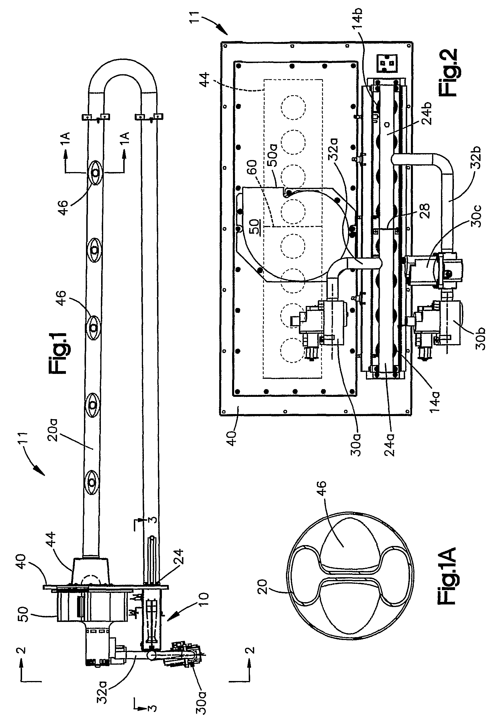
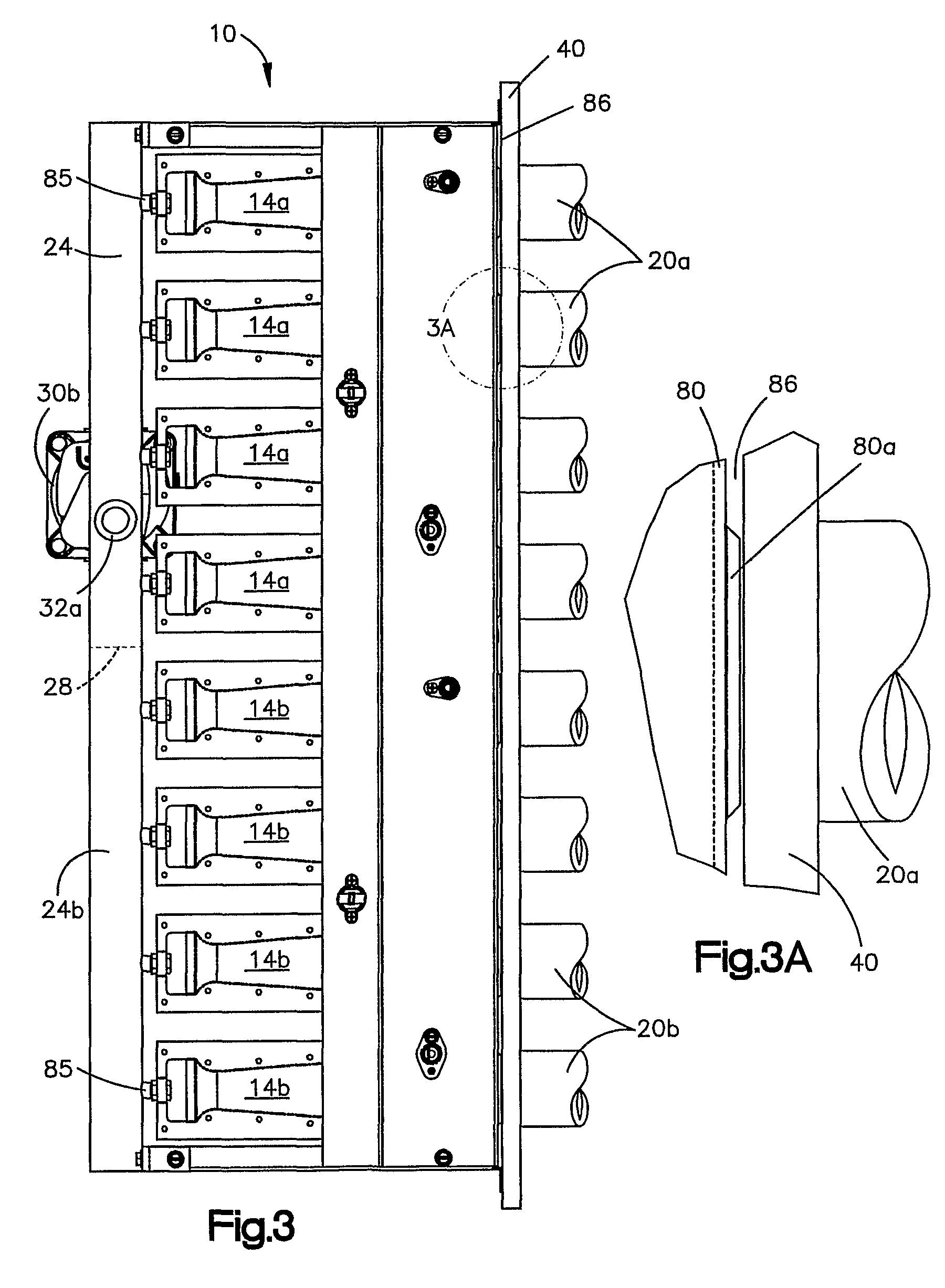
[0029]FIGS. 1-4 illustrate the overall construction of a heating module 11 constructed in accordance with a preferred embodiment of the invention. The illustrated module is intended to be mounted in a duct and heats air traveling through the duct.

[0030]The module includes a burner assembly 10, which as seen best in FIG. 3, comprises a plurality burner units 14a, 14b, which fire into and heat associated heat exchanger tubes 20a, 20b (see FIG. 4). In the illustrated embodiment, the heat exchanger tubes 20a, 20b are substantially identical in construction. When referring to a heat exchanger tube in general, it will be referred to by the reference character 20. The burners 14a, 14b are more fully disclosed in U.S. Pat. No. 5,186,620, entitled “Gas Burner Nozzle,” which is also owned by the assignee of the present invention and which is hereby incorporated by reference.

[0031]The burners 14a, 14b are fed a combustible gas from a manifold assembly 24. In accordance with the invention, the ...


PUM


Abstract

A gas fired furnace capable of operating with a 16:1 turndown ratio or greater. The furnace includes a plurality of burners (10) grouped into at least (14a) first and second (14b) groups, each group connected to a source of combustible gas through a control valve (30a, 30b, 30c). The control valve (30c) controlling at least one group of burners is of a modulating type having an output proportional to a control signal applied to the valve. The burners fire into associated heat exchange tubes (20a), each tube having an inlet (24) and an outlet. The tube outlets are connected to a collector chamber (44) that includes a baffle plate (60) that divides the collector into two sections, one of the sections communicating with the outlets of the tubes associated with the first group of burners, the other section communicating with the outlets of the heat exchanger tubes associated with the other group of burners.

Description

TECHNICAL FIELD[0001]The present invention relates generally to heating apparatus and, in particular, to a gas fired furnace having multiple burners.BACKGROUND ART[0002]Furnaces utilizing gas fired, “inshot” type burners are in common use today. One application for this type of furnace includes the heating of air circulating through a duct. Duct heating furnaces generally include one or more heat exchange tubes that are positioned in the air duct and heat the air as it is circulated through the duct.[0003]The inshot burners fire into inlets of the heat exchange tubes. The products of combustion are drawn through the tubes by an induced draft blower which is connected to a flue or other discharge conduit through which the products of combustion are discharged.[0004]It is desirable that the furnace be capable of a variable output so that a relatively constant air temperature can be maintained in the duct. If the furnace is only capable of operating at one BTU level, large swings in ai...

Claims


Application Information

Patent Timeline
Patent Type & Authority Patents(United States)
IPC IPC(8): F23Q9/08F23D14/04F23D23/00F24H3/08
CPCF23D14/045F24H3/087F23D23/00F23N2037/02F23N2237/02
Inventor SLABY, TERRANCE C.
Owner BECKETT GAS
Why Eureka
Try Eureka