Flexible walled cannula

a cannula and flexible technology, applied in the field of surgical instruments and cannulas, can solve the problems of limited the ability of the cannula to accommodate an instrument, the circular or semi-circular incision is generally not self sealing, and the deformation cannot be easily accommodated, so as to reduce the need for sutures, reduce the trauma to the surgical site, and reduce the effect of fluid leakag

Inactive Publication Date: 2010-12-07
SYNERGETICS
View PDF22 Cites 38 Cited by
  • Summary
  • Abstract
  • Description
  • Claims
  • Application Information

AI Technical Summary

Benefits of technology

[0014]To accomplish the foregoing and other objects of the embodiments of this invention there is provided a flexible walled cannula apparatus and method of use in combination with an obturator especially designed for use with and during ophthalmic surgery. Although the apparatus is especially suited for use with and during ophthalmic surgery it may be utilized with and during a plurality of other surgical procedures. As aforesaid, the present art provides embodiments that when compared with the prior art uniquely allows use of larger width instruments through smaller slits or flat incisions than previously have been commonly used, reduce fluid leakage when the instrument is removed from the cannula (i.e. vitreous humor, aqueous humor, or saline during ophthalmic surgery), further reduce the requirement for sutures after the cannula is removed, reduce trauma to the surgical site due to the small slit incision size utilized for the cannula, and thereby promotes a faster healing of the surgical site.
[0019]The obturator of the present art in combination with the cannula uniquely allows a surgeon to form an incision, insert the cannula, and remove the obturator in a manner that is quicker and less traumatic than in the prior art. The blade portion of the present art obturator has a dulled side and a protrusion opposite the dulled side along with a cutting edge. The cutting edge ensures a slit or substantially flat incision while the dulled side and protrusion protects the cannula from cutting edge damage during cannula insertion and obturator withdrawal.
[0020]For larger instruments (i.e. smaller gauge size), the present art utilizes one or more valves in conjunction with the cannula in order to ensure a seal when the cannula is placed. Limitations of a pinch or compression seal of the cannula tube are found when instruments of approximately 20 gauge are utilized with the present art cannula. An embodiment of the present art places a flexible sheet material having a slit onto or with the cannula head which provides one or more leaflets which seal the cannula and thereby function as a valve. The sheet material has a preferable disc form and is partially covered with a cap, both of which are preferably adhesively attached with the head. In a preferred embodiment, the slit in the sheet is of an arcuate semi-circular form with an at least partially perpendicular (to a tangent of the arc) cut towards the edge of the disc. The valve portion, including the sheet with a slit, reduces any fluid leakage from the organ yet provides a surgeon with the flexibility to utilize larger diameter or width surgical instruments. Preferably, said sheet material valve is formed from a silicone sheet material but for alternative embodiments may be formed from any one or more of a plurality of bio-compatible flexible materials.
[0021]When used in conjunction with the valve, in an embodiment, the obturator of the present art has a notched or reduced diameter portion which serves as a seat for the valve when the obturator is inserted through the cannula. In such a position, one or more of the formed valve leaflets mate with the notch to allow a less deformed position for the leaflets than when such leaflets are positioned on the larger diameter portion of the obturator. In a preferred embodiment, the notched portion allows the valve to maintain a substantially relaxed position prior to cannula use, which assists in producing a positive valve seal and thereby allows reduced fluid leakage when such cannula is in use. One or more of the formed valve leaflets mate with the notch to provide an optimum fluid seal.

Problems solved by technology

Typically, the prior art is manufactured from a substantially rigid polyimide or stainless steel material or tubing which does not easily accommodate the deformation necessary for insertion of an instrument that violates the envelope (i.e. inside diameter) of the cannula tube or tubing.
Prior art methods of attaching or mounting the cannula tube with the cannula head also limited cannula deformation and thereby limited the ability the cannula to accommodate an instrument which violates the cannula envelope.
Unfortunately, said circular or semi-circular incision is generally not self sealing when the cannula is removed, except for approximately 25 gauge incisions.
If the incision, hole, or wound is not self sealing, sutures are required to close the wound, which procedure is generally more invasive and traumatic to the patient.

Method used


Image

  • Flexible walled cannula
  • Flexible walled cannula
  • Flexible walled cannula

Examples


Embodiment Construction

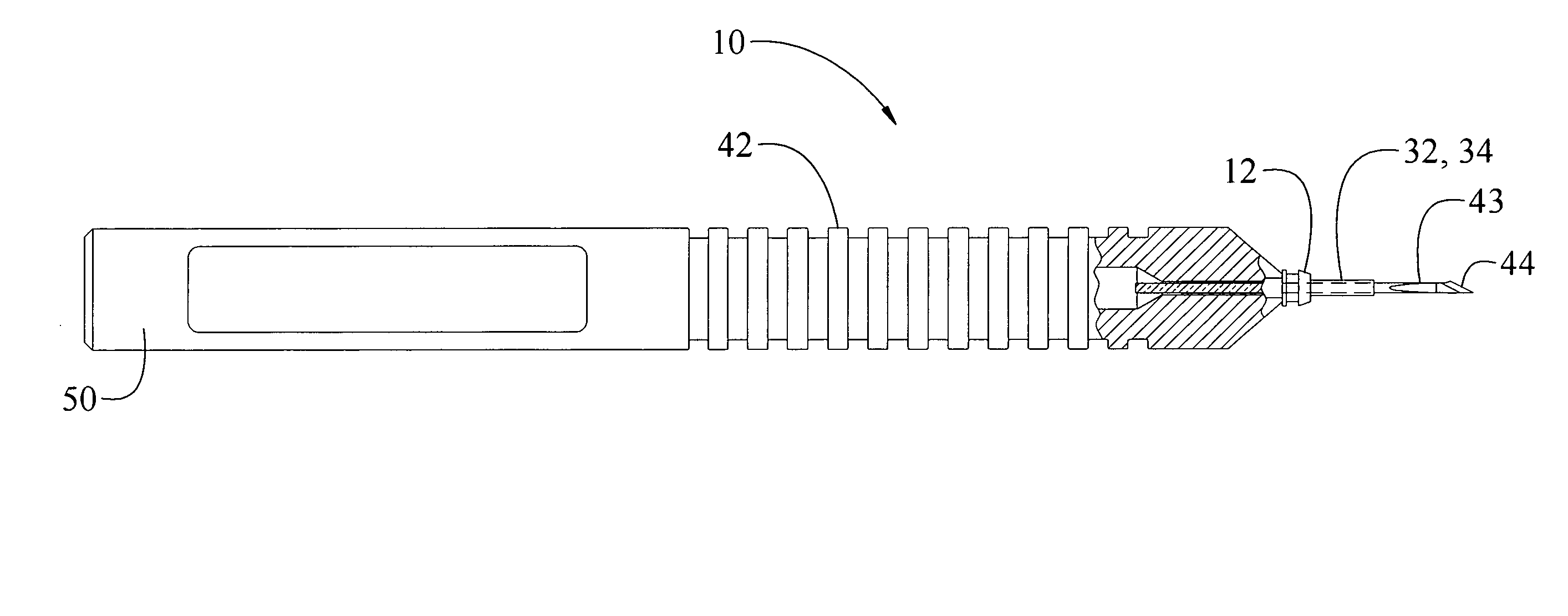
[0044]Referring now to the drawings, there is shown in FIGS. 1-4, 7-9 a preferred embodiment of the flexible walled cannula 10 of the present art and in FIGS. 5, 6, 10&11 an alternative embodiment of the present art showing the cannula 12 and obturator 42 and in FIGS. 12-19 an alternative embodiment showing the cannula valve 39 and associated elements thereof.

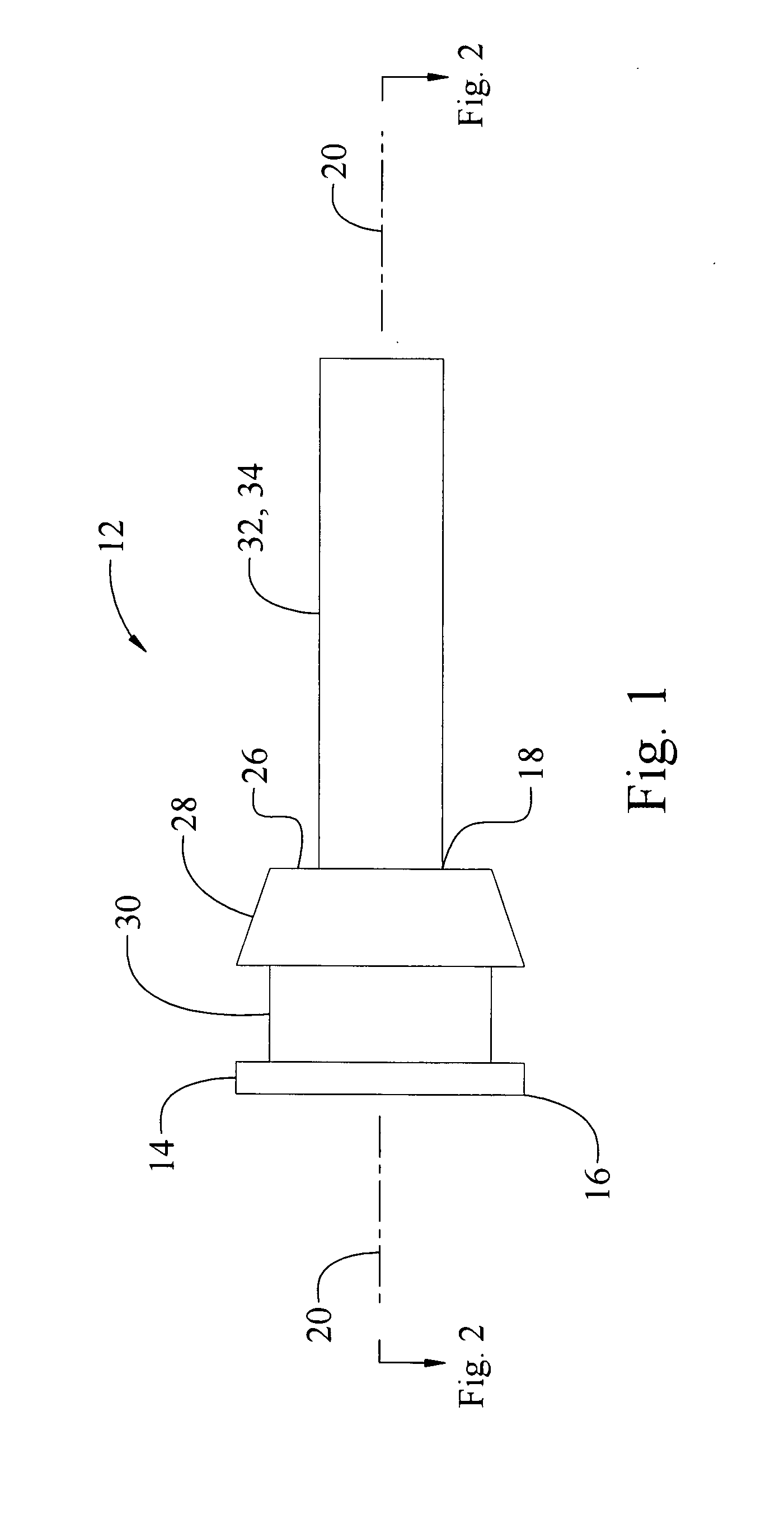
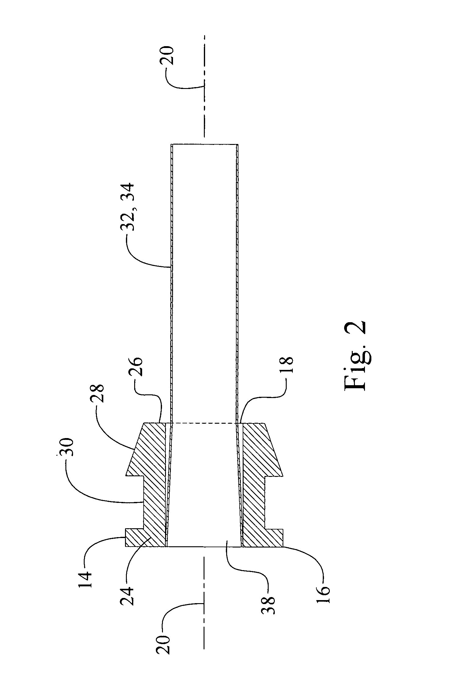
[0045]The preferred embodiment of the present art comprises a cannula 12 having a head 14 which can be of a plurality of shapes or forms with a connected or attached cannula tube 32 of a flexible or elastic material, all in combination with a uniquely formed obturator 42 which shares some similarities with a conventional microvitreoretinal (MVR) blade. Said head 14 may be manufactured from a plurality of materials including but not limited to metals and alloys thereof, rubbers, plastics, woods, composites, ceramics, or a combination thereof, or any suitable material. Preferably said head 14 is of a round button like shape 16, p...


PUM


Abstract

A flexible walled cannula apparatus and method of use comprising a uniquely deformable cannula tube and head in combination with a uniquely shaped obturator which allows the use of heretofore unusable larger gauge surgical instruments while providing a self sealing incision. The apparatus and method of use provides a preassembled obturator and cannula assembly with which the surgeon forms an incision or channel, inserts the cannula tube, and through the cannula inserts surgical instruments to perform a surgical operation. The apparatus and method of use is especially suited for ophthalmic surgical operations. Alternative embodiments for use with even larger diameter instruments utilize a uniquely designed valve having leaflets which prevent bodily or other fluid leakage from the cannula when an instrument is not inserted.

Description

[0001]This application claims priority of U.S. Provisional Patent Application No. 60 / 816,065, entitled Flexible Walled Cannula filed Jun. 23, 2006.BACKGROUND OF THE INVENTION[0002]The art of the present invention relates to surgical instruments and cannulas for surgical use and more particularly to a flexible cannula which substantially seals with or within an incision and allows a surgical instrument of a width or dimension greater than the inside round undeformed diameter of the cannula to fit through the cannula via elastic deformation of said cannula while continually sealing the incision through which said cannula is placed. The present art utilizes a combination of a uniquely modified microvitreoretinal blade or obturator assembled in conjunction with the flexible cannula whereby a self sealing and substantially flat incision is created for placement and use of said cannula. The substantially flat incision in combination with the flexible cannula allows a surgeon to create a l...

Claims


Application Information

Patent Timeline
IPC IPC(8): A61M5/178
CPCA61B17/3421A61F9/0133A61B17/3431A61F9/007B33Y80/00
Inventor NADOLSKI, TIMOTHYAWH, CARLDIEKEMPER, JEFFREY R.
Owner SYNERGETICS
Why Eureka
Try Eureka