Hand held appliance

a hand-held, appliance technology, applied in air heaters, lighting and heating apparatus, apparel and other directions, can solve the problems of fluid passing, pressure loss within the appliance, recirculating within the space, etc., to reduce fluid leakage, reduce stray fluid flow, and mitigate the ingress of ducts

Inactive Publication Date: 2016-11-24
DYSON TECH LTD
View PDF4 Cites 8 Cited by
  • Summary
  • Abstract
  • Description
  • Claims
  • Application Information

AI Technical Summary

Benefits of technology

[0018]In a preferred embodiment, the seal and the second seal extend around the switch assembly and the inner wall. This holds the switch assembly in place with respect to the inner wall. In addition, when the outer wall is slid into position over the inner wall, and the first seal and second seal are squashed between the two walls, the first and second seals provide a seal above and below the switch assembly thus reducing fluid leaks into the fluid flow path via the user interface.
[0019]Preferably, the switch assembly comprises a flexible membrane which surrounds the actuator and comprises a protrusion that seals against the inner wall. Preferably, the protrusion extends along a longitudinal axis of the inner wall. In a preferred embodiment, the protrusion extends either side of the actuator along the longitudinal axis of the inner wall. In this embodiment, the user interface is sealed both radially and longitudinally to reduce stray fluid flow and also to mitigate ingress of and duct etc. into the fluid flow path at the user interface.
[0020]Preferably a further seal is provided. This further seal is preferably provided downstream of the fluid inlet and spaced from the seal. The seal is provided to prevent fluid from recirculating between the outer wall and the inner wall so, the seal is proud of either the radially outer surface of the inner wall or the radially inner surface of the outer wall. This can cause the outer wall to rock or pivot about the seal with respect to the inner wall. For this reason a further seal is provided which centralises the outer wall with respect to the inner wall and mitigates any rocking or pivoting.
[0021]In one embodiment the functions of the second seal and the further seal are combined; thus the second seal both seals the user interface and mitigates rocking or pivoting of the outer wall with respect to the inner wall.

Problems solved by technology

In the arrangement of having an outer wall and an inner wall, there is an issue with fluid passing in the space between the outer wall and the inner wall and recirculating within this space.
Any recirculation causes pressure losses within the appliance and impacts the velocity and volume of fluid exiting the appliance.

Method used


Image

  • Hand held appliance
  • Hand held appliance
  • Hand held appliance

Examples


Embodiment Construction

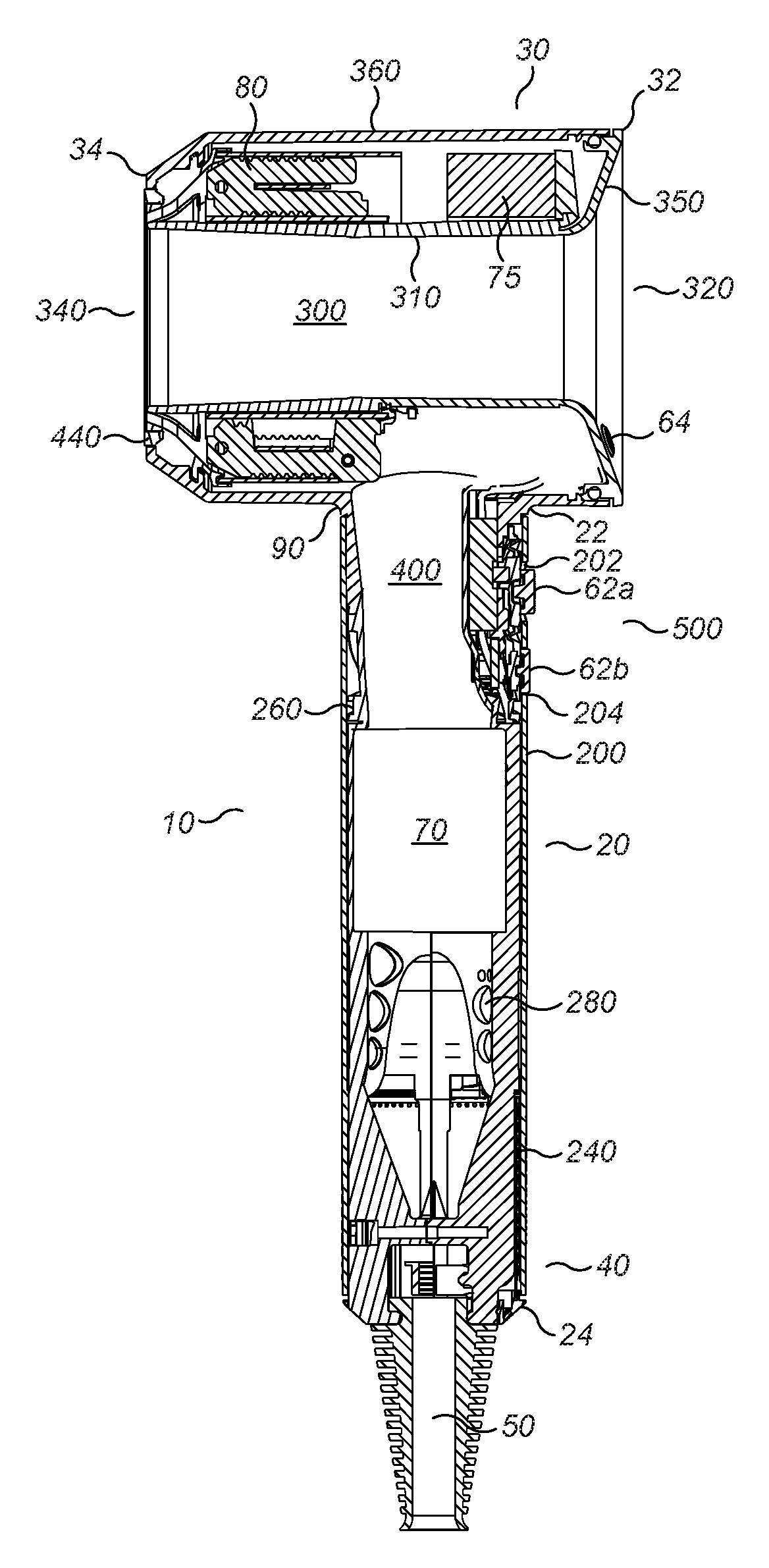
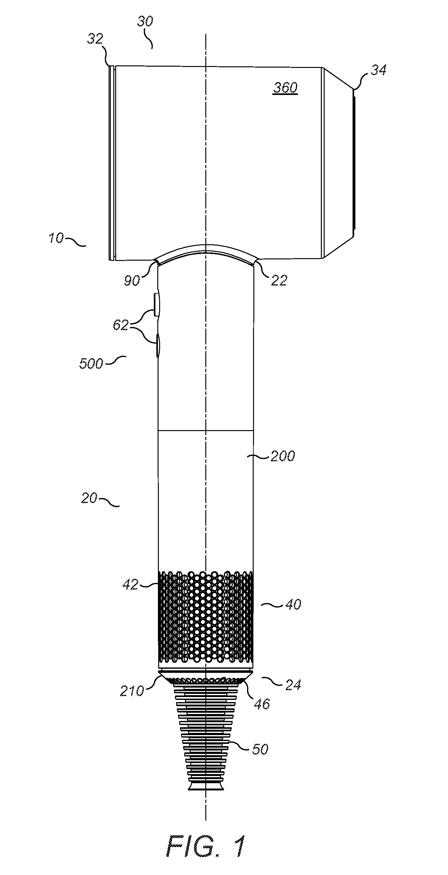
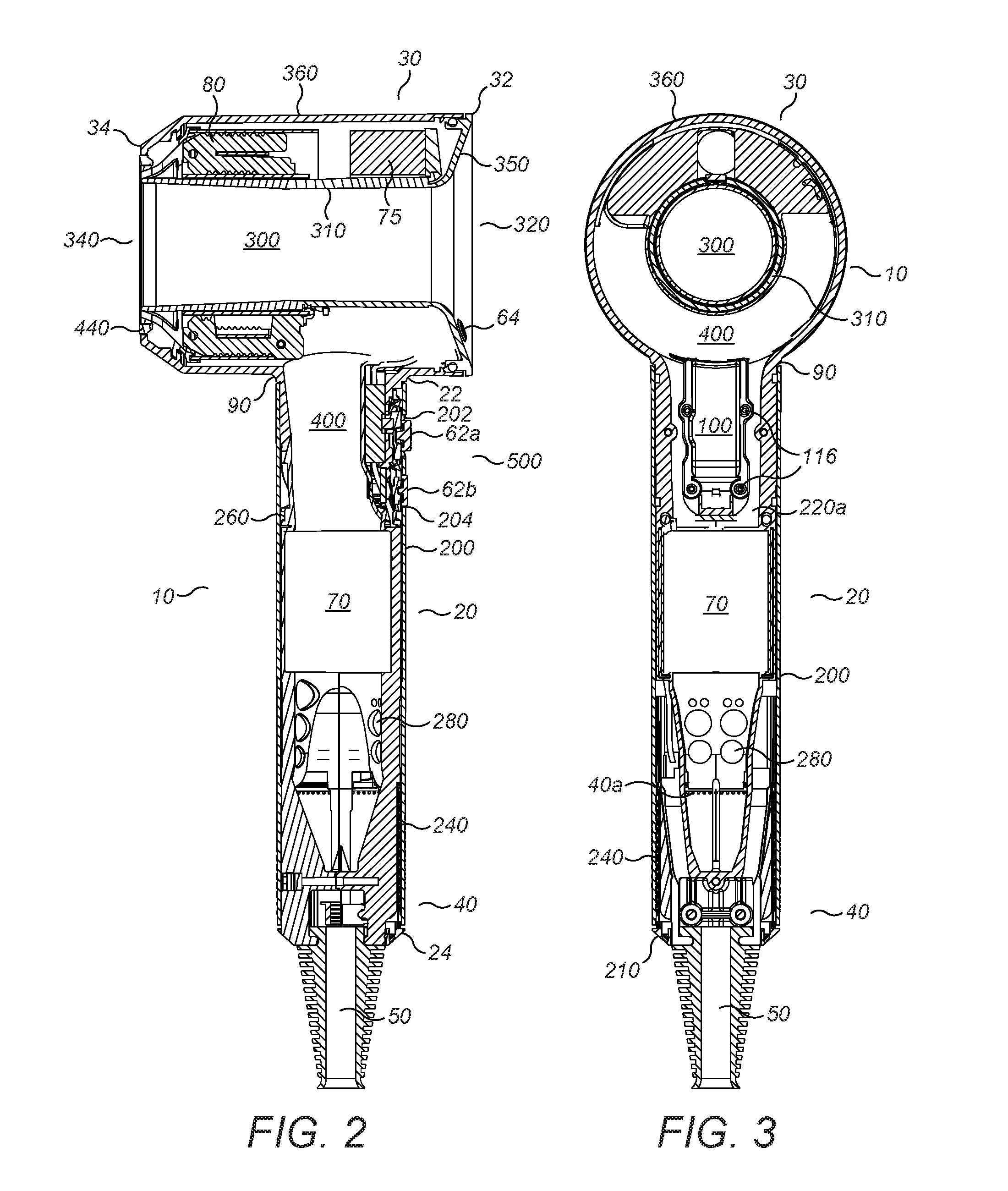
[0032]FIGS. 1, 2 and 3 show a hairdryer 10 with a handle 20 and a body 30. The handle has a first end 22 which is connected to the body 30 and a second end 24 distal from the body 30 and which includes a primary fluid inlet 40. Power is supplied to the hairdryer 10 via a cable 50. At a distal end of the cable 50 from the hairdryer 10 a plug (not shown) is provided, the plug may provide electrical connection to mains power or to a battery pack for example.

[0033]The handle 20 has an outer wall 200 which extends from the body 30 to a distal end 24 of the handle. At the distal end 24 of the handle an end wall 210 extends across the outer wall 200. The cable 50 enters the hairdryer through this end wall 210. The primary fluid inlet 40 in the handle 20 includes first apertures that extend around and along 42 the outer wall 200 of the handle and second apertures that extend across 46 and through the end wall 210 of the handle 20. The cable 50 is located approximately in the middle of the e...


PUM


Abstract

A hand held appliance comprising an outer wall, an inner wall, a fluid flow path extending within the inner wall from a fluid inlet into the appliance to a fluid outlet, a fan unit disposed within the inner wall for drawing fluid in through the fluid inlet and a seal disposed between the outer wall and the inner wall. Fluid in the fluid flow path may flow from the fluid inlet to an upstream end of the fan unit, through the fan unit to a downstream end of the fan unit and on to a fluid outlet. The seal may be downstream of the fluid inlet. The seal may be downstream of the fan unit. The outer wall may comprise a handle of the appliance. The seal may comprise an o-ring, a lip seal or any over moulded seal.

Description

REFERENCE TO RELATED APPLICATIONS[0001]This application claims the priority of United Kingdom Application No. 1508810.7, filed May 22, 2015, the entire contents of which are incorporated herein by reference.FIELD OF THE INVENTION[0002]This invention relates to hand held appliance and in particular a hair care appliance.BACKGROUND OF THE INVENTION[0003]Generally, a motor and fan are provided which draw fluid into a body; the fluid may be heated prior to exiting the body. The motor is susceptible to damage from foreign objects such as dirt or hair so conventionally a filter is provided at the fluid inlet to the blower. The fan and heater require power in order to function and this is provided via internal wiring from either a mains power cable or batteries attached to the appliance.SUMMARY OF THE INVENTION[0004]Embodiments of the invention provide a hand held appliance comprising an outer wall, an inner wall, a fluid flow path extending within the inner wall from a fluid inlet into th...

Claims


Application Information

Patent Timeline
Patent Type & Authority Applications(United States)
IPC IPC(8): A45D20/10
CPCA45D20/10A45D20/12A45D20/122F24H3/04F24H3/0423
Inventor ATKINSON, ANTOINE FRANCOISHEDGES, CHRISTOPHER WILLIAM
Owner DYSON TECH LTD
Why Eureka
Try Eureka