Hydrostatic rotary cylinder engine

a rotary cylinder engine and axial compensation technology, applied in the direction of rotary piston engines, engine lubrication, toothed gearings, etc., can solve the problems of unsatisfactory volumetric efficiency and loud noise, unoptimized axial compensation of hydraulic forces acting axially on the rotary valve by the compensating piston, etc., to reduce production costs, reduce the slight increase in friction, and eliminate deficiencies

Inactive Publication Date: 2010-11-16
WILLIBALD ARTUR
View PDF7 Cites 4 Cited by
  • Summary
  • Abstract
  • Description
  • Claims
  • Application Information

AI Technical Summary

Benefits of technology

[0005]It is the object of the invention to eliminate these deficiencies and at the same time to reduce the slightly increased friction on the rotary valve due to the orbital movement and to reduce the production costs.

Problems solved by technology

However, comprehensive experiments have shown that this concept which initially appears striking cannot be realized in practice at high operating pressures because the necessary eccentric movement of the rotary valve relative to the stationary control panel does not permit sufficiently accurate commutation of the machine.
Greatly varying torque output at the shaft, unsatisfactory volumetric efficiency and loud noises are the result since the outer part of the eccentric gear must operate in the high pressure range.
Furthermore, the axial compensation of the hydraulic forces acting axially on the rotary valve by the compensating piston was not optimal owing to the eccentric movement of the rotary valve.
Since the tooth systems of the eccentric gear produce a displacement effect similar to that in the case of an internal gear pump, it is unfavorable, owing to the hydrostatic losses resulting there, if this displacement takes place in the high-pressure part of the machine.

Method used


Image

  • Hydrostatic rotary cylinder engine
  • Hydrostatic rotary cylinder engine
  • Hydrostatic rotary cylinder engine

Examples


Embodiment Construction

[0045]Below, possible working examples are explained with reference to several figures, some of which show a single embodiment in different views with different degrees of detail, reference being made in some cases to reference numerals already mentioned in preceding figures.

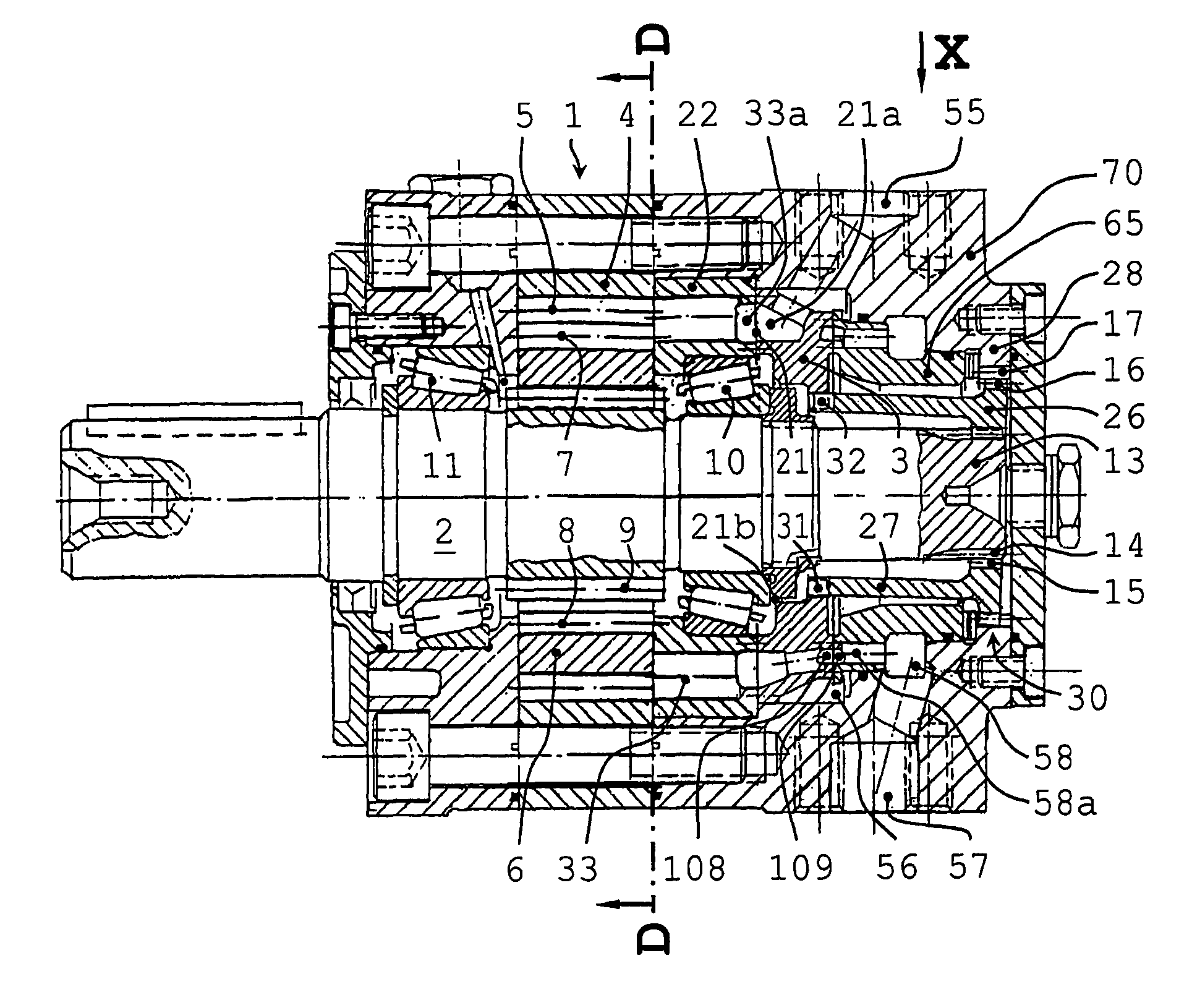
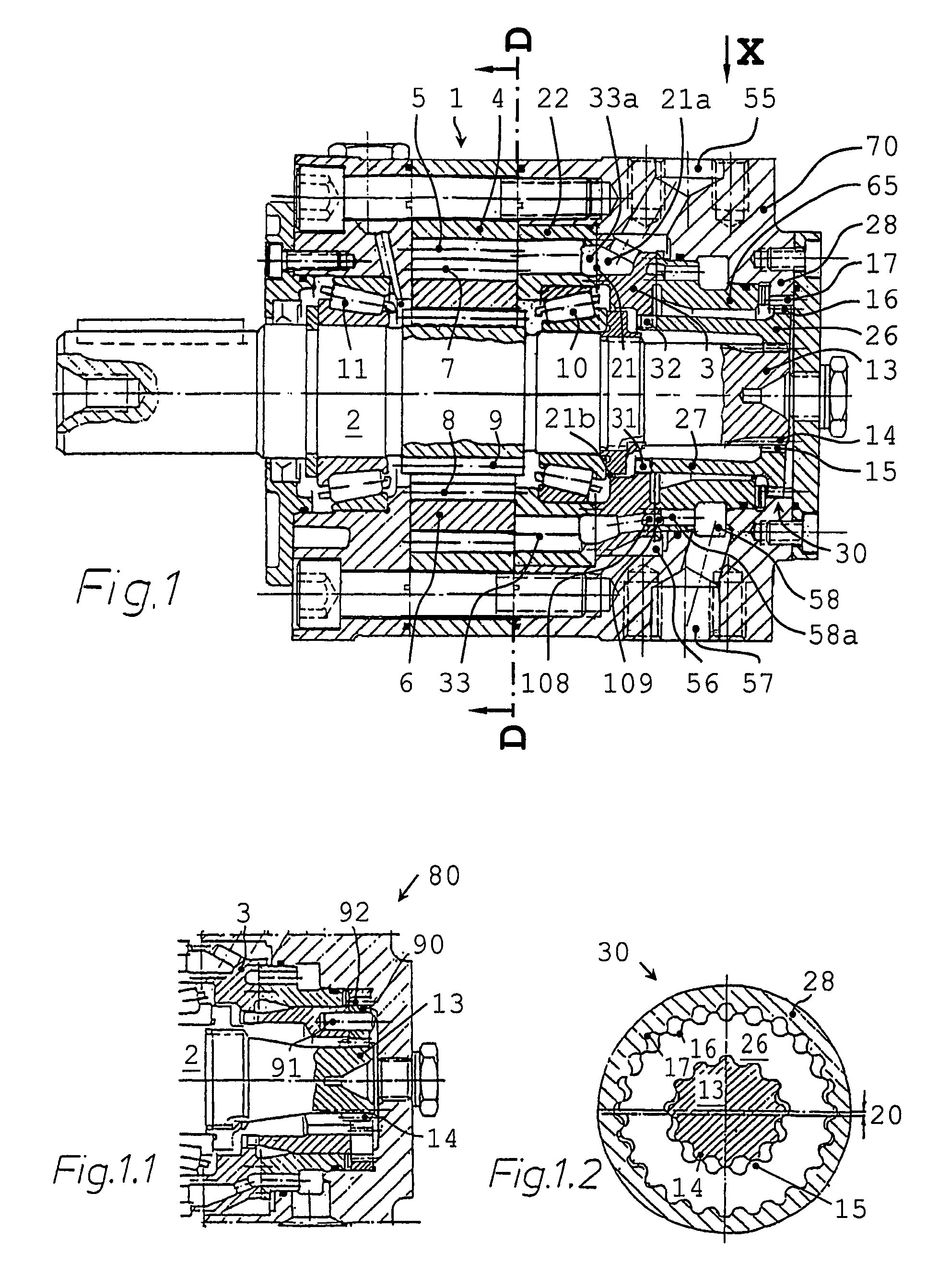
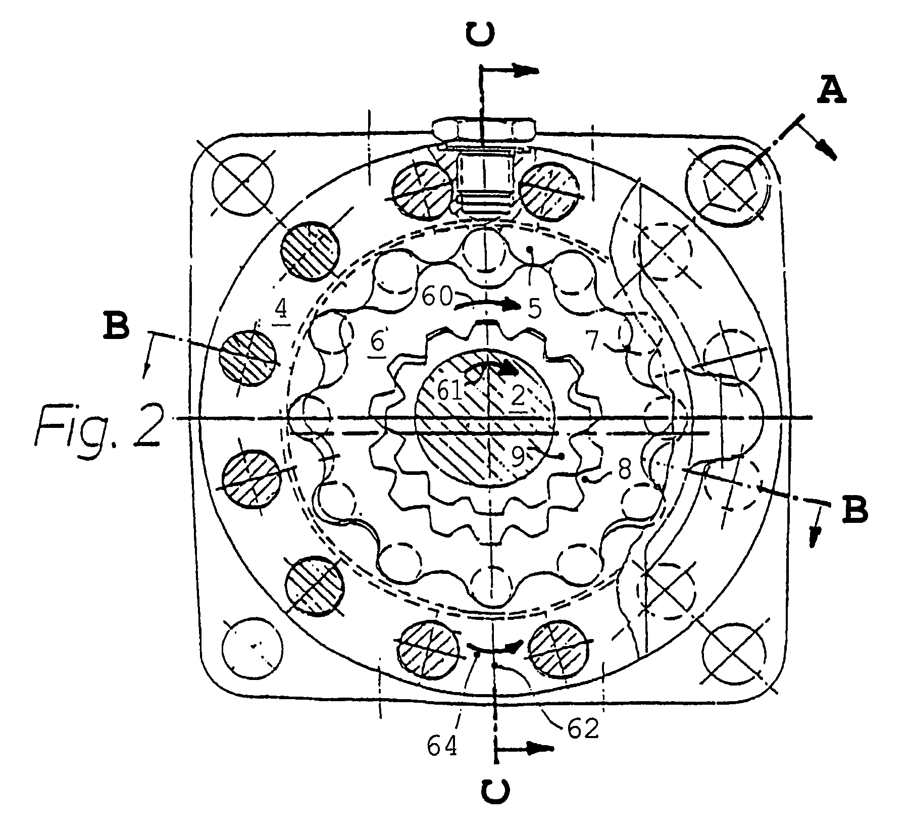
[0046]FIG. 1 shows a first working example of a rotary cylinder engine according to the invention having an eccentric gear in a longitudinal section, while FIG. 2 shows a cross-section through the rotor-stator system of the first working example along the section line D-D of FIG. 1. Furthermore, FIG. 2 shows the section direction of FIG. 1 from the section line C-C. The rotor-stator system of the power part 1 of the rotary cylinder engine comprises a central, stationary stator 4 having an inner tooth system 5, referred to below as first inner toothed system 5, which is engaged at least partly by a rotary piston 6 which is arranged eccentrically for executing an orbital movement, acts as a rotor and has an outer ...


PUM


Abstract

The invention relates to a hydrostatic, slow-speed rotary cylinder engine comprising a power part (1) which acts as an output, said power part comprising a central, stationary stator (4), a rotary cylinder (6) which is used as a rotor and a shaft (2) which is mounted in a central manner on both sides of the roller bearings (10, 11) which are arranged directly adjacent to the power part (1). Supply and discharge of tooth chambers comprising the working fluid is controlled by means of a disk-shaped rotational valve (3) which is mounted in a continuously centered manner in relation to the shaft (2) and the stator (4). A toothed wheel drive is arranged between a shaft external toothing (14) and an internal toothing (17) of a stationary internal toothed ring (28; 92) as a synchronous drive for the rotational valve (3). The toothed wheel drive is subsequently arranged in the leakage oil region of the engine and is formed by a planetary gear (80) or, preferably, by an eccentric gear (30).

Description

[0001]This application is the national phase under 35 U.S.C. §371 of PCT International Application No. PCT / EP2005 / 007543, which has an International filing date of Jul. 12, 2005, and designated the United States of America, which claims priority to Swiss application No. CH 01239 / 04, filed on Jul. 22, 2004, each of which is incorporated herein by reference in its entirety.FIELD OF THE INVENTION[0002]The invention relates to a hydrostatic, low-speed rotary cylinder engine according to the preamble of independent claims 1 and 2.BACKGROUND OF THE INVENTION[0003]A hydrostatic rotary cylinder machine of this type is disclosed in EP 1 074 740 B1. An advantage of the formation of a rotary cylinder machine disclosed there over earlier solutions is that the roller bearings of that part of the shaft which is under high hydrostatic load are arranged directly adjacent with a small axial spacing in the stationary housing so that a very small degree of bending deformation and tooth deformation on ...

Claims


Application Information

Patent Timeline
Patent Type & Authority Patents(United States)
IPC IPC(8): F03C2/00F03C4/00F04C2/00F03C2/22F04C2/10
CPCF03C2/22F04C2/105
Inventor EISENMANN, SIEGFRIED A.
Owner WILLIBALD ARTUR
Why Eureka
Try Eureka