
Connector with conductor piercing prongs for a solar panel

a solar panel and conductor technology, applied in the field of systems, can solve the problems of difficult installation of small solar power systems on residential rooftops, insufficient space for installers, and difficulty in small solar power systems, and achieve the effects of increasing energy output 5-25%, high conversion efficiency, and increasing resilience to dust and debris

Inactive Publication Date: 2010-11-02
SKY RICH STAR LTD
View PDF15 Cites 92 Cited by
  • Summary
  • Abstract
  • Description
  • Claims
  • Application Information

AI Technical Summary

Benefits of technology

[0016]The micro-inverters are configured on the back of each solar panel. Each micro-inverter converts DC power generated by its respective solar panel to grid-compliant AC power and are known to exhibit high conversion efficiency. Moreover, there are no moving parts to wear out or maintain.
[0017]In addition, unlike prior art string systems, the solar panels of the present invention operate a maximum power point tracking (MPPT), increasing energy output 5-25%. They also exhibit an increased resilience to shade, dust and debris and are capable of high levels of power production even in variable light conditions. By incorporating a micro-inverter into each solar panel, each solar panel produces power independently of the others; thus, eliminating the possibility that a single point failure will disable the entire system. The micro-inverters have a very low internal temperature rise and a long lifetime. They also eliminate the space, heat, noise and visual concerns with large string inverter systems.
[0018]Furthermore, by using the compression connector fittings, the solar panels are easy to install and dramatically reduced installation cost, time and space. The system of the present invention offers maximum flexibility in that solar panels can be easily added in any quantity, orientation, location even to any existing solar system.

Problems solved by technology

Some installations leave insufficient space to allow the installer to make the connections reliably.
The installation of such a system is quite complicated and typically requires the services of a licensed electrician or certified solar installer.
There is also a difficulty with small solar power systems on residential rooftops.
Gables and multiple roof angles make it difficult on some houses to obtain enough area having the same exposure angle to the sun for a system of 2 kW.
A similar problem arises where trees or gables shadow one portion of an array, but not another.
While a variety of proposals directed at PV AC modules have previously been made, none have includes a simple efficient means for connecting to the utility grid.
Prior art models of PV AC modules suffer poor reliability owing to early failure of the electrolytic capacitors that are used to store the solar cell energy before it is converted to AC.
Moreover, such PV AC modules do not include a simple and efficient means for connection to the utility grid.

Method used


Image

  • Connector with conductor piercing prongs for a solar panel
  • Connector with conductor piercing prongs for a solar panel
  • Connector with conductor piercing prongs for a solar panel

Examples


Embodiment Construction

[0032]The present invention overcomes many of the prior art problems associated with solar panel arrays. The advantages, and other features of the systems and methods disclosed herein, will become more readily apparent to those having ordinary skill in the art from the following detailed description of certain preferred embodiments taken in conjunction with the drawings which set forth representative embodiments of the present invention and wherein like reference numerals identify similar structural elements.

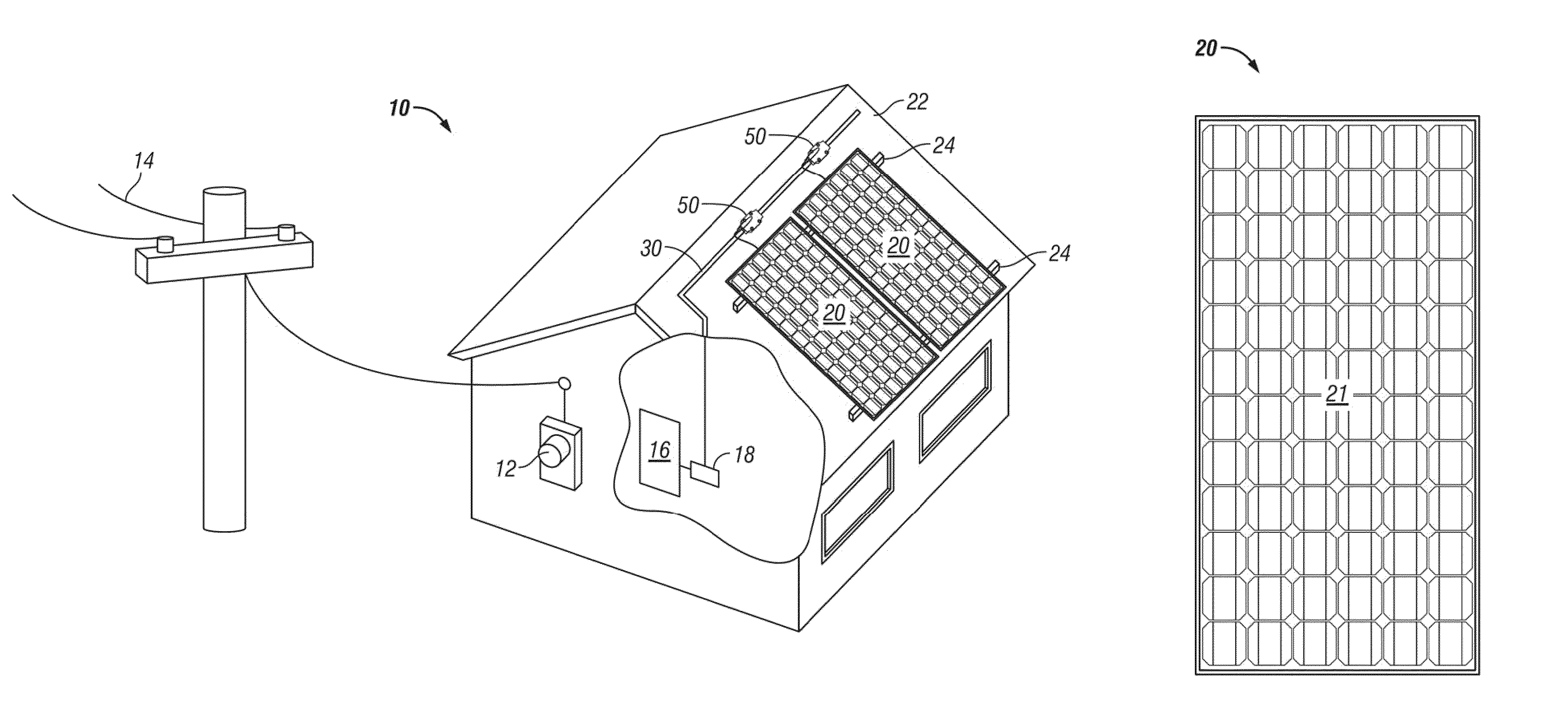
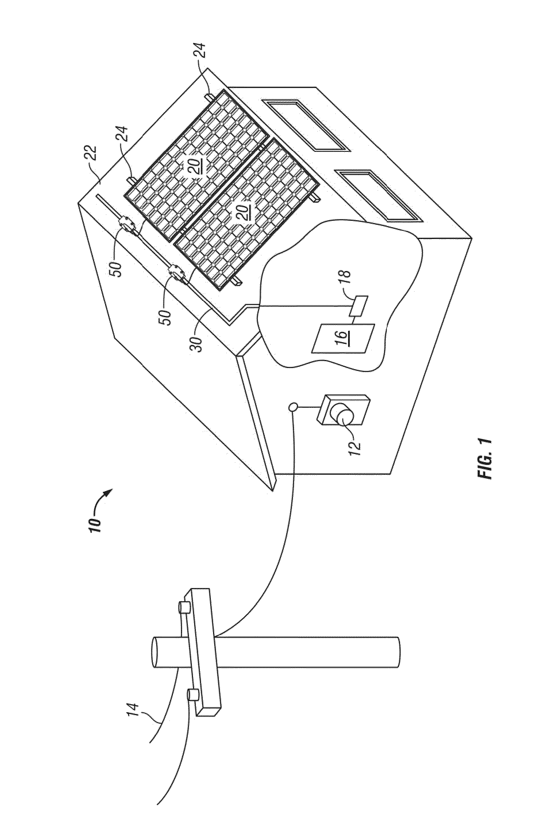
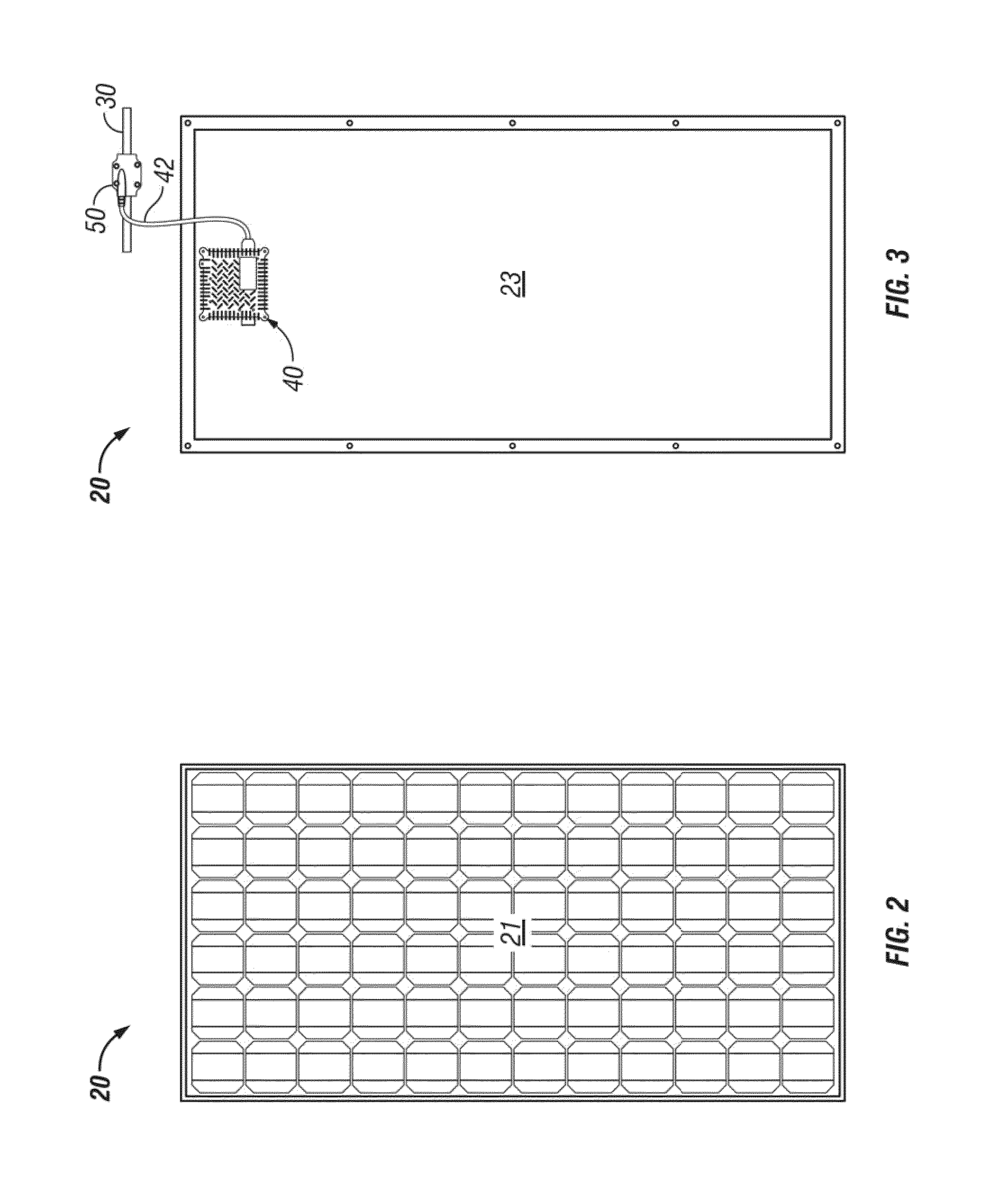
[0033]With reference to the Figures, and in particular to FIG. 1, an embodiment of the system 10 of the present invention is depicted. The system 10 includes one or more solar panels 20 mounted on a support rack 24 configured on the roof 22 of a building. The support rack 22 may comprise wooden boards or metal tubing sufficient to displace the solar panels 20 above surface of the roof 22. Suspending the solar panels 20 above the surface of the roof 22 allows air to freely circul...


PUM


Abstract

The present invention comprises an electrical connector device for electrically connecting an alternating current (“AC”) photovoltaic (“PV”) solar panel device having an integral micro-inverter to the utility grid. The electrical connector device is a compression connector fitting that includes an upper and lower housing, which each include a channel for receiving the main electrical conductor line. The electrical connector device further includes three electrical prong, which are designed to pierce and penetrate the insulation of the main electrical conductor line to establish an electrical connection between the micro-inverter and the utility grid, when the electrical connector device is compressed about the main electrical conductor line. The shape of the channel formed in the electrical connector device has a distinctive cross-sectional shape that substantially corresponds to the shape of the main electrical conductor line to insure proper alignment and orientation of the main conductor line within the connector device.

Description

CROSS-REFERENCE TO RELATED APPLICATION[0001]This application is a continuation-in-part of U.S. patent application Ser. No. 12 / 542,600, filed on Aug. 17, 2009, the technical disclosure of which is hereby incorporated herein by reference.BACKGROUND OF THE INVENTION[0002]1. Technical Field of the Invention[0003]The present invention relates to systems for utilizing power generated by solar panels, and more particularly, to an improved electrical connector for use in a modularized photovoltaic system. The invention provides an electrical connector for quickly and efficiently connecting a fully integrated and self-contained alternating current (“AC”) photovoltaic (“PV”) solar panel device to an electrical conductor line that allows photovoltaic applications to become true plug-and-use devices.[0004]2. Description of the Related Art[0005]Most of today's solar photovoltaic (PV) power sources are utility connected. About 75% of these installations are residential rooftop systems with less t...

Claims


Application Information

Patent Timeline
Patent Type & Authority Patents(United States)
IPC IPC(8): H01R12/00
CPCH01L31/02021H01R4/2404Y02E10/50H01R4/2406
Inventor BROWDER, JOHN H.
Owner SKY RICH STAR LTD
Learn More