
Bellows for hydraulic, hydropneumatic, or pneumatic piston-cylinder units

a technology of hydraulic and hydropneumatic pistons, applied in the direction of machines/engines, mechanical equipment, shock absorbers, etc., can solve the problems of outgoing air terminating and incoming air also arriving from the wheel well, and achieve the effect of simple design

Inactive Publication Date: 2010-11-02
ZF SACHS AG
View PDF19 Cites 7 Cited by
  • Summary
  • Abstract
  • Description
  • Claims
  • Application Information

AI Technical Summary

Benefits of technology

"The present invention provides an improved bellows for hydraulic, hydropneumatic, or pneumatic piston-cylinder units. The bellows allows air to be drawn in only when there is relative movement, without any extra assembly work. The end area of the piston rod is connected to the interior of the bellows through a flow connection, which ensures that clean air is obtained. The design is simple and advantageous because the flow connection consists of a transverse bore and a longitudinal bore. The bellows can be sealed and held in place appropriately on the adjacent components. The technical effect of the invention is to provide a reliable and efficient air management system for hydraulic, hydropneumatic, or pneumatic piston-cylinder units."

Problems solved by technology

Because the vibration dampers or MacPherson strut units are exposed in the wheel well of the vehicle to water spray and dirt, the use of a bellows can protect the piston rod, but, according to the state of the art, the disadvantage is that incoming air also arrives from this wheel well, and the outgoing air terminates in it.

Method used


Image

  • Bellows for hydraulic, hydropneumatic, or pneumatic piston-cylinder units
  • Bellows for hydraulic, hydropneumatic, or pneumatic piston-cylinder units
  • Bellows for hydraulic, hydropneumatic, or pneumatic piston-cylinder units

Examples


Embodiment Construction

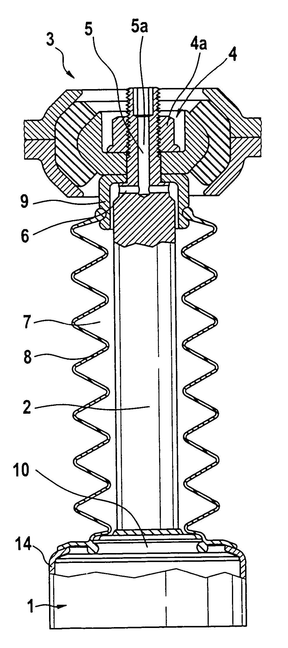
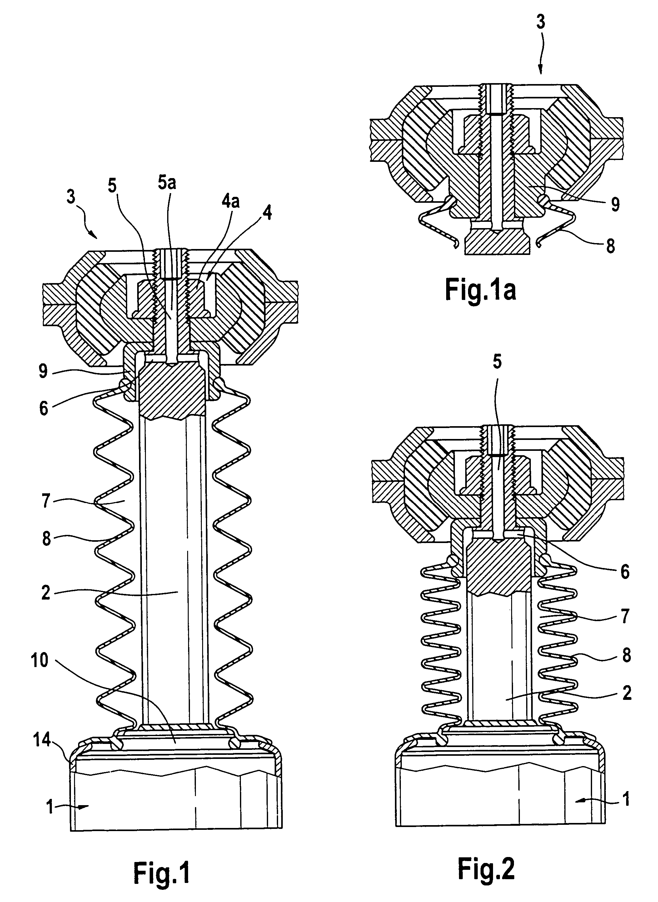
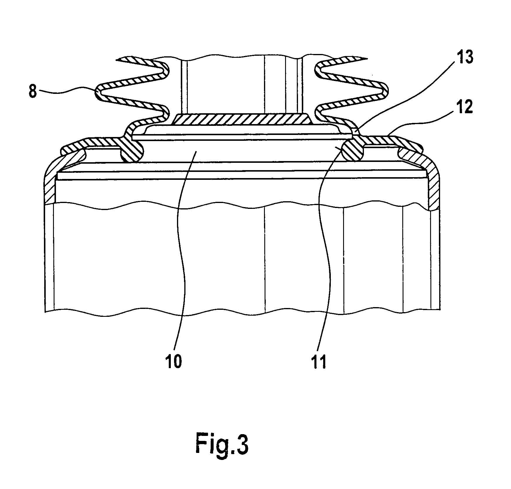
[0017]FIG. 1 shows a piston-cylinder unit 1 including a container tube 14 in which the individual parts (not shown in detail) of the vibration damper itself are located. A piston rod 2 projects out from this container tube 14, the upper end of the piston rod 2 extending through an upper mounting bearing 3. The upper mounting bearing 3 is attached to the body of a vehicle, whereas the lower area of the piston-cylinder unit with the piston rod 2 and the bellows 8 is located in a wheel well of the vehicle. A longitudinal bore 5a of a flow connection 5 in an upper end area of the piston rod 2 leads to the area outside the wheel well, e.g., to the area underneath the hood. The longitudinal bore 5a is connected to the interior space 7 of the bellows 8 by a transverse bore 6. Air thus escapes the interior space 7 of the bellows 8 to the outside via the transverse bore 6 and the longitudinal bore 5a of the flow connection 5, when the piston rod 2, as shown in FIG. 2, moves into the containe...


PUM


Abstract

A bellows for hydraulic, hydropneumatic, or pneumatic piston-cylinder units, especially for vibration dampers or MacPherson strut units for motor vehicles, is located between the end of a piston rod and a cylinder, and covers the part of the piston rod which projects out from the cylinder to provide protection against dirt and / or damage. An interior space of the bellows undergoes a change in volume as a result of the relative movement of the piston and cylinder. The end area of the piston rod distal from the cylinder includes at least one flow connection leading to the interior of the bellows. The flow connection allows an incoming and / or outgoing flow of air. The end area of the piston rod, i.e., the end which passes through a mounting bearing connecting the piston-cylinder unit to the body of the vehicle, is provided with a flow connection connecting the interior space of the bellows to the atmosphere.

Description

BACKGROUND OF THE INVENTION[0001]1. Field of the Invention[0002]The invention pertains to a bellows for hydraulic, hydropneumatic, or pneumatic piston-cylinder units, especially for vibration dampers or MacPherson strut units for motor vehicles, wherein the bellows is located between the end of the piston rod and the cylinder and covers the part of the piston rod which projects out from the cylinder to provide protection against dirt and / or damage. The interior space of the bellows undergoes a change in volume as a result of the relative movement of the parts with respect to each other and at least one flow connection leading to the interior of the bellows is provided to allow an incoming and / or outgoing flow of air.[0003]2. Description of the Related Art[0004]Bellows for piston-cylinder units are already known, for example, from German Patent Document DE 102 00 608 A1. In these cases, a vibration damper or a MacPherson strut unit is provided with a bellows for protection against di...

Claims


Application Information

Patent Timeline
Patent Type & Authority Patents(United States)
IPC IPC(8): F16F9/38F16F9/00F16J3/04
CPCF16F9/38F16J3/046F16F9/00
Inventor BECK, HUBERT
Owner ZF SACHS AG
Learn More