Power factor correction method for AC/DC converters and corresponding converter

a technology of ac/dc converter and power factor correction, which is applied in the direction of ac-dc conversion, ac-electronic conversion, electric variable regulation, etc., can solve the problems of input impedance change and input impedance change, and achieve the effect of reducing the size of the transformer, reducing the switching current and losses in the chopper or inverter connected ahead of the converter

Inactive Publication Date: 2010-10-26
TALLINN UNIVERSITY OF TECHNOLOGY
View PDF7 Cites 24 Cited by
  • Summary
  • Abstract
  • Description
  • Claims
  • Application Information

AI Technical Summary

Benefits of technology

[0013]The advantage of the method for current shaping described above is in a fact that there is no measurement of the current or voltage instantaneous values needed. It is only necessary to provide the required ratio between mains voltage and instantaneous power as well as between instantaneous values of voltage and current in smoothing filter. Keeping the required ratios with reasonable accuracy is possible by implementing a converter with parallel and series resonance alternation. The converter with parallel and series resonance alternation has an inversely proportional dependence between output voltage and current. But this is valid only if the rate of changes of the current or voltage in output circuit is less by 1 to 2 orders compared to mains frequency. As inversely proportional dependence on the converter output is needed for frequency not lower, but higher than mains frequency, so the converter must have a higher frequency power supply. To increase the frequency, a frequency-increasing unit is connected ahead of the converter with parallel and series resonance alternation. The frequency increment also gives one more good effect—elimination of the main drawback of the converter with parallel and series resonance alternation that is a large weight and size of converter's transformer, coil and capacitor.
[0014]At high frequency, converter with parallel and series resonance alternation is not functioning more as a higher harmonics filter in mains current like it was at mains frequency. The useful effect is produced here as a result of using of the inversely proportional dependence between output voltage and current of the converter. The frequency-increasing unit having converter with parallel and series resonance alternation is connected between rectifier bridge and smoothing filter for rectified voltage. The supply voltage of the frequency-increasing unit is not a constant DC voltage, as it is common, but there are unsmoothed half-waves of mains voltage, which are pulsating from zero to amplitude value of mains voltage. The frequency-increasing unit could be implemented as a single chopper or inverter. Chopper is preferred at small powers, as it contains only one power transistor and it is very simple. At larger powers, an inverter is more practical, as it is possible to load converter with more power compared to chopper. The output voltage of the chopper or inverter is a square wave with modulated amplitude.
[0018]If it is needed to supply many galvanically separated and different voltage loads, so it is possible to provide transformer of the converter with parallel and series resonance alternation with additional secondary winding pairs and bridge rectifiers connected further. This way, it is possible to stabilize the voltage of one load by means of frequency-increasing unit and feedback circuit.
[0019]The converter based on the described method also provides additional advantages.
[0020]As the converter with parallel and series resonance alternation also includes transformer, then along with power factor correction, the galvanic separation from mains and required voltage level are obtained. This way, the overall simplicity of the solution is achieved.
[0023]Fourth advantage is a fact that the switching currents and losses in chopper or inverter connected ahead of the converter are reduced because of the using of the converter with parallel and series resonance alternation.

Problems solved by technology

This causes changing of the input impedance.
It also causes changing of the input impedance.

Method used


Image

  • Power factor correction method for AC/DC converters and corresponding converter
  • Power factor correction method for AC/DC converters and corresponding converter
  • Power factor correction method for AC/DC converters and corresponding converter

Examples


Embodiment Construction

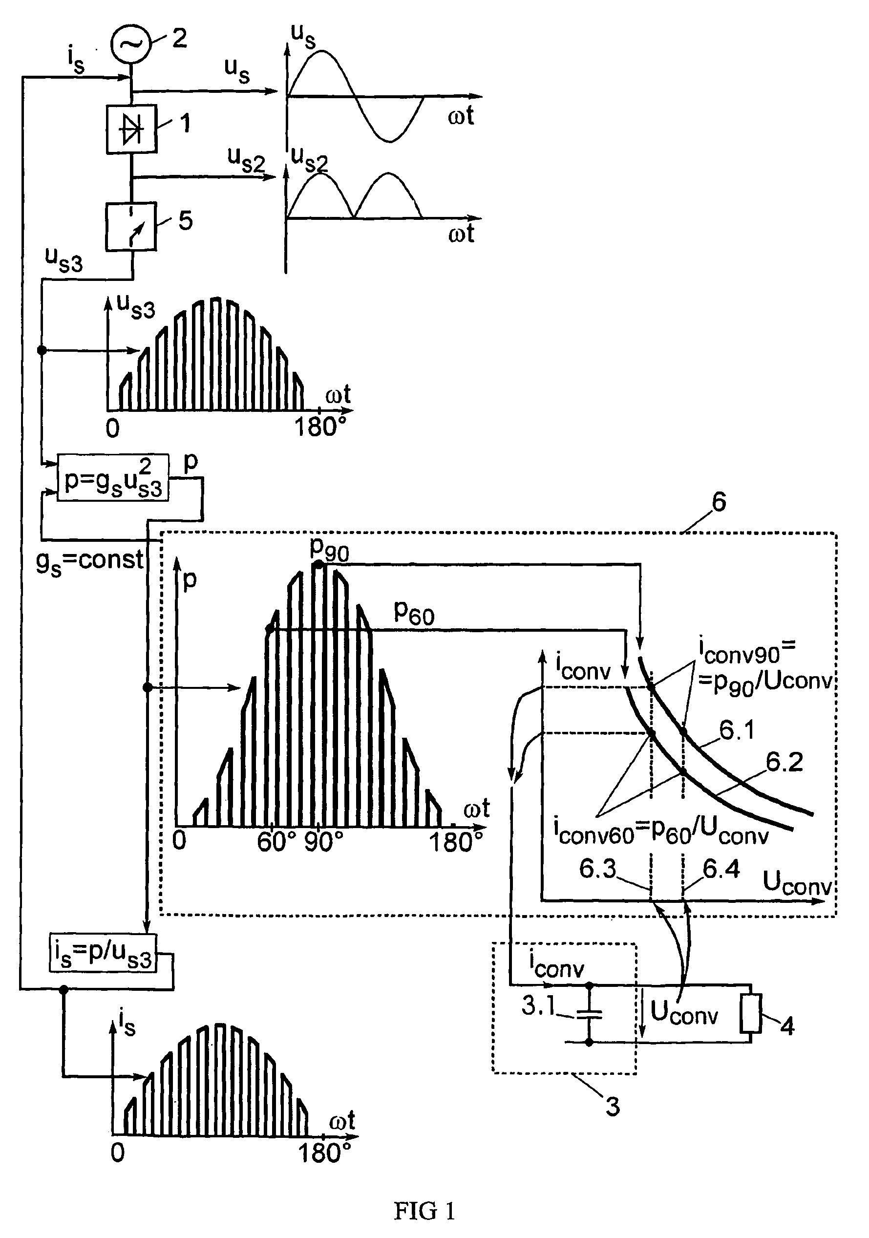
[0038]In the FIG. 1, there is shown generalized method for power factor correction in AC / DC converters. Alternating voltage us supplied from the mains 2 is delivered then to rectifier 1. After rectifying an unsmoothed half-waves of the mains voltage us2 are obtained. The rectified and smoothed voltage is delivered from smoothing filter 3 to load 4. To improve the power factor, the rectified voltage is not delivered directly to the smoothing filter 3. At first, the shape of the voltage us2 is changed by means of chopper 5. Hereby, DC voltage pulse train us3 appears wherein amplitude of the pulses is changing according to the instantaneous value of mains voltage. This pulse train is delivered to the converter circuit 6, which is able to change voltage-current relation analogously to transformer. The input admittance gs of this converter circuit is constant and it consumes instantaneous power p from the mains, which could be defined by multiplication of the input admittance gs and volt...


PUM


Abstract

An indirect and passive method for AC / DC converter power factor correction is disclosed. The correction is achieved by stabilizing the input impedance of the converter with keeping the inversely proportional dependence between the current iconv(t) and voltage uconv(t) of the output smoothing filter (3). The necessary dependence is achieved by natural characteristics of circuit with passive components. An uncontrolled converter (6) with alternation of parallel and series resonance is used as such circuit. To increase the operating frequency of this converter, a chopper or an inverter is used. The resonant converter decreases the commutation current of the switches. Output voltage is easy to control by pulse width modulation of chopper or inverter. Passive power factor correction results in the total harmonic distortion of main current THDi=10 to 40 per cent. All currents of the converter are limited naturally in all operating modes.

Description

RELATED APPLICATIONS[0001]This application is a national phase application of PCT Application Ser. No. PCT / EE2005 / 000010 filed Dec. 13, 2005, which, in turn, claims priority to Estonian Application No. P200400124, filed Dec. 14, 2004. Each of these applications is herein incorporated in its entirety by reference.TECHNICAL FIELD[0002]The present invention relates to the power electronics and can be used in AC / DC converters to reduce distortion of AC side current and thus, to improve the power factor of the converters. The invention is particularly useful in converters with frequent short circuit operating, e.g., in power supplies for electric arcs.BACKGROUND ART[0003]There are known passive power factor correction methods that use a network frequency LC resonance circuits operating as a higher frequency harmonic filter. For instance, a higher harmonics filter is connected in series with a bridge rectifier on its AC side (A. R. Prasad, P. D. Ziogas, S. Manias. Passive input current wa...

Claims


Application Information

Patent Timeline
Patent Type & Authority Patents(United States)
IPC IPC(8): H02M7/06H02M1/00H02M1/42
CPCH02M1/4241H02M1/4258Y02B70/126Y02B70/10
Inventor JANSON, KUNOJARVIK, JAANSHKLOVSKI, JEVGENI
Owner TALLINN UNIVERSITY OF TECHNOLOGY
Why Eureka
Try Eureka