
CO2 cooling and heating apparatus and method having multiple refrigerating cycle circuits

a technology of refrigerating cycle circuit and cooling apparatus, which is applied in the direction of machine operation mode, indirect heat exchanger, light and heating apparatus, etc., can solve the problems of unstable operation of refrigerator and inability to produce high-temperature heat source simultaneously, and achieve stable control of operation and improve the coefficient of performance

Inactive Publication Date: 2010-10-26
MAYEKAWA MFG CO LTD +1
View PDF20 Cites 9 Cited by
  • Summary
  • Abstract
  • Description
  • Claims
  • Application Information

AI Technical Summary

Benefits of technology

The present invention relates to a cooling and heating apparatus with multiple refrigerating cycle circuits that use CO2 as a refrigerant. The invention provides a method for cooling and heating that produces a high temperature heat source and a very low temperature cold source simultaneously with stable control and improved coefficient of performance. The invention includes a first refrigerating cycle circuit that uses a compressor to compress the CO2 refrigerant to the supercritical region, a condenser to condense the refrigerant, an expansion device to further cool the refrigerant, and an evaporator to sublimate the refrigerant. The invention also includes a second refrigerating cycle circuit that uses a compressor to compress the refrigerant, a second expansion device to further cool the refrigerant, and a second evaporator to sublimate the refrigerant. The invention also includes a third refrigerating cycle circuit that uses a compressor to compress the refrigerant, a third expansion device to further cool the refrigerant, and a third evaporator to sublimate the refrigerant. The invention provides a more efficient and effective cooling and heating apparatus that uses CO2 as a refrigerant.

Problems solved by technology

Although References 1 and 2 disclose supplying cooling fluid to cooling loads, a high-temperature heat source cannot be produced simultaneously.
Further, as the CO2 refrigerant is expanded to the pressure / temperature level of the CO2 triple point to reduce the CO2 refrigerant to a two-phase mixture of solid CO2 and CO2 gas, and the latent heat of sublimation of the solid CO2 is used to cool the cooling fluid, the refrigerant flow path can clog or the refrigerant flow path can lose pressure, resulting in unstable operation of the refrigerator.

Method used


Image

  • CO2 cooling and heating apparatus and method having multiple refrigerating cycle circuits
  • CO2 cooling and heating apparatus and method having multiple refrigerating cycle circuits
  • CO2 cooling and heating apparatus and method having multiple refrigerating cycle circuits

Examples


first embodiment

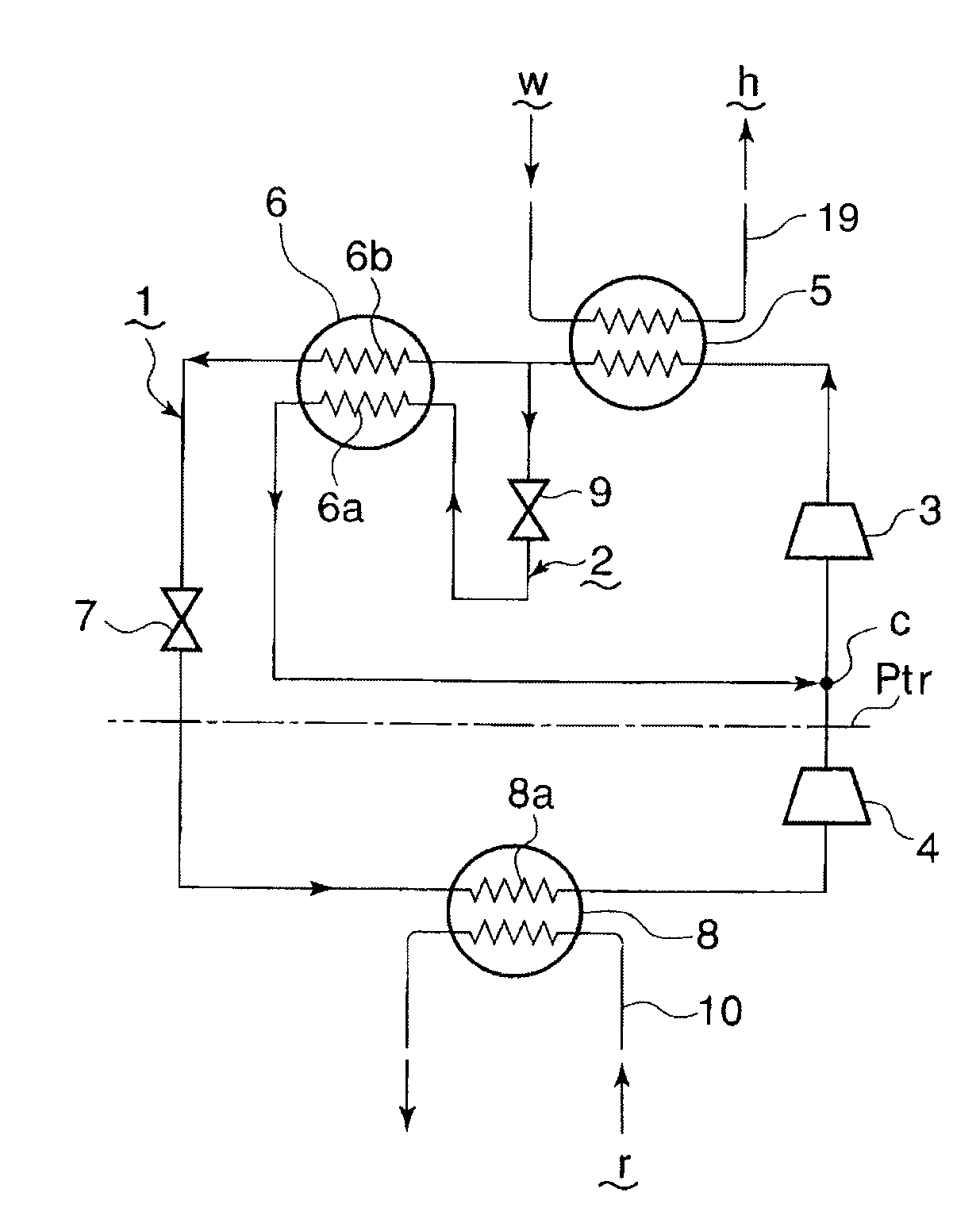
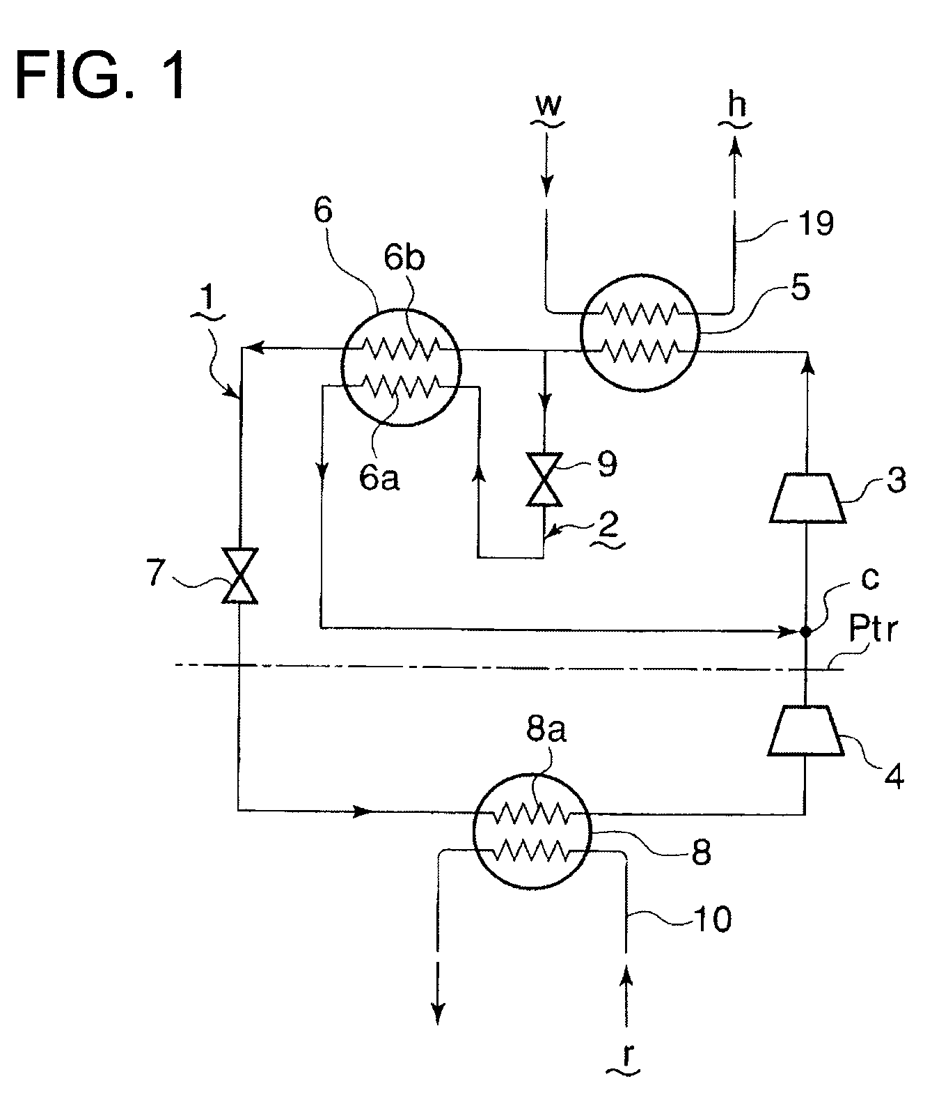
[0030]Referring to FIG. 1, which shows the first embodiment, reference numeral 1 is a refrigerant flow path of a first refrigerating cycle circuit using CO2 as a refrigerant, and 2 is a refrigerant flow path of a second refrigerating cycle circuit also using CO2 as a refrigerant. Reference numeral 3 is a high-pressure stage compressor for both the first and second refrigerating cycle circuits, 4 is a low-pressure stage compressor for the first refrigerating cycle circuit, and 5 is a condenser for both the first and second refrigerating cycle circuits. Reference numeral 6 is an intermediate cooler. The refrigerant flow path 2 (hereafter referred to as the second refrigerant flow path) of the second refrigerating cycle circuit branches off from the refrigerant flow path 1 (hereafter referred to as the first refrigerant flow path) of the first refrigerating cycle circuit at a point upstream of the intermediate cooler 6 and is connected via an expansion valve 9 to an evaporating part 6a...

second embodiment

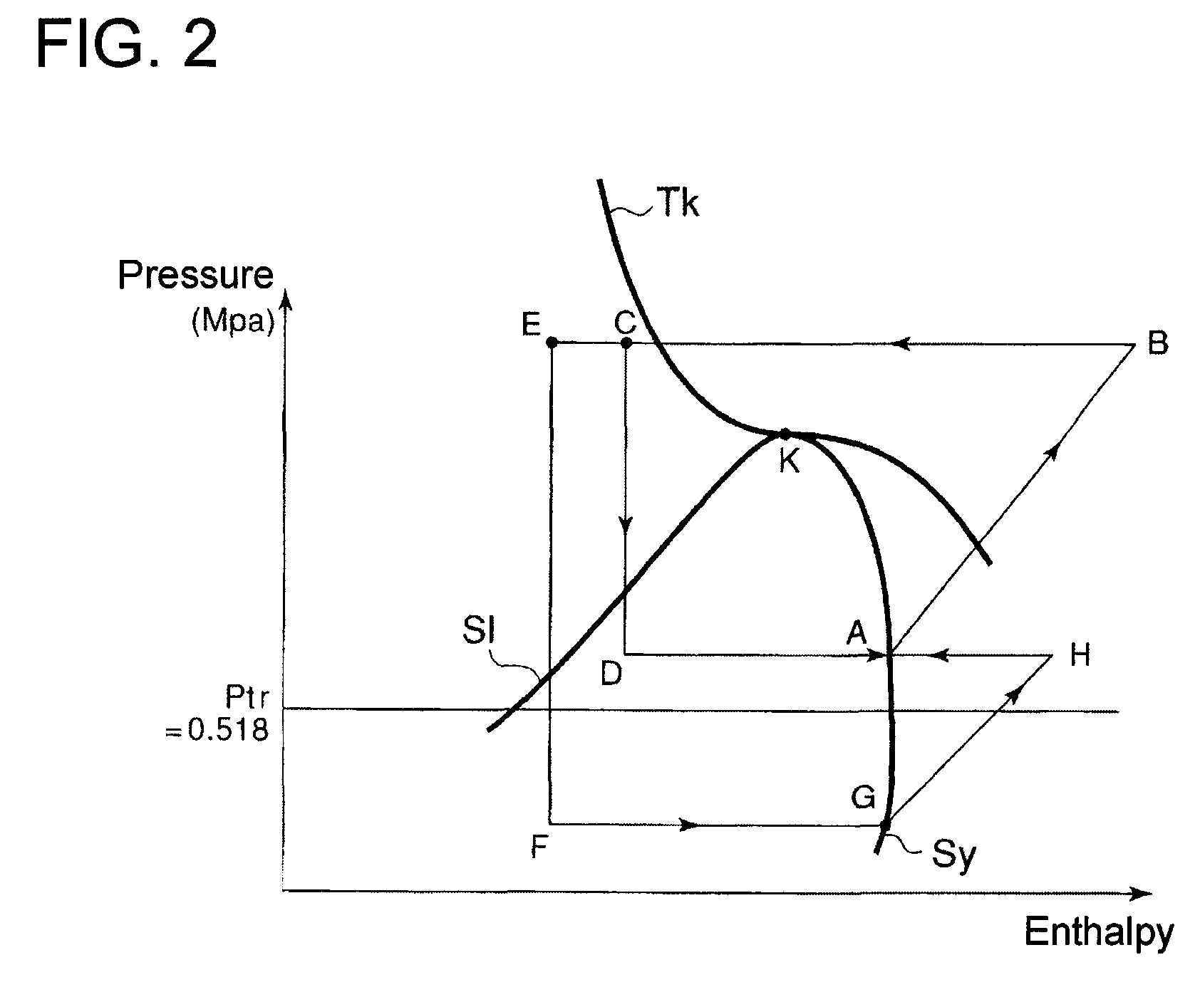
[0038]The operation of the second embodiment will be explained with reference to the P-h diagram of FIG. 4. The high-pressure stage compressor 3 compresses the refrigerant to the supercritical region (I→J in FIG. 4). Then the compressed refrigerant is cooled (J→L in FIG. 4) through water w flowing through the condenser 5. The refrigerant cooled in the condenser 5 is introduced to the intermediate cooler 6 and then to the second intermediate cooler 12. Thus, the refrigerant is cooled in two stages (L→C and C→E in FIG. 4) and condensed. The condensed refrigerant is expanded through the expansion valve 7 to the pressure / temperature level of the CO2 triple point or lower (E→F in FIG. 4).

[0039]On the other hand, the refrigerant branched before entering the intermediate cooler 6 and expanded through the expansion valve 9 flows into the evaporating part 6a of the intermediate cooler 6, where the branched refrigerant flash evaporated through the expansion is fully evaporated and joins the r...

third embodiment

[0045] heated water of about 80° C. for hot-water supply and cooling fluid of a very low temperature of −56° C.˜−78° C. for cooling loads can be produced simultaneously. As the first refrigerating cycle circuit 21 and the second refrigerating cycle circuit 31 are operated in the region of pressure / temperature above the CO2 triple point, solid CO2 does not develop and increase in refrigerant flow resistance or clogging does not occur, and stable refrigerating operation is assured. As the second refrigerating cycle circuit 31 is operated using ammonia or HC as a refrigerant, the cycle circuit can be operated with high efficiency.

[0046]The fourth embodiment will be explained with reference to FIG. 6, FIG. 7A, and FIG. 7B. In the fourth embodiment further adds to the third embodiment shown in FIG. 5, a fourth refrigerating cycle circuit 51 in which CH gas or air or nitrogen gas can be used as a refrigerant, thereby enabling supply of extremely low temperature cold heat source. In FIG. 6...


PUM


Abstract

A CO2 cooling and heating apparatus and method permit simultaneous production of high-temperature heat source and low-temperature heat source having a temperature difference therebetween. The apparatus / method uses CO2 (carbon dioxide) as a refrigerant, and has a first refrigerating cycle circuit where the refrigerant is compressed to a supercritical zone and then decompressed via an expansion device to a pressure / temperature level of the CO2 triple point or below to thereby attain evaporation. The apparatus can include multistage compressors, intermediate cooler disposed in a first refrigerant flow path between a condenser and the expansion device. A second refrigerating cycle circuit having a second refrigerant flow path, which can branch off from the first refrigerant flow path or provided in an independent closed circuit, can be provided to carry out absorption of evaporation latent heat with the first refrigerant flow path to thereby maintain the pressure / temperature level of the CO2 triple point (Ptr) or above. A third refrigerating cycle circuit having a third refrigerant flow path also can be provided to carry out heat exchange with the second refrigerant flow path.

Description

[0001]This is a continuation of International Application PCT / JP2006 / 320566 having an international filing date of 16 Oct. 2006, which claims priority to JP 2005-302346 filed on 17 Oct. 2005. The disclosure of the priority application, in its entirety, including the drawings, claims, and the specification thereof, is incorporated herein by reference.BACKGROUND[0002]A dual cooling device, comprising two refrigerating cycles of a high-temperature side and a low temperature side cycles, has been used to supply cooling fluid cooled to a very low temperature, in the range of minus tens of degrees C. For example, Japanese Laid-Open Patent Application No. 2004-170007 (hereafter Reference 1) discloses a refrigerator system that uses combined ammonia and CO2 refrigerating cycles, where its high-temperature side refrigerating cycle uses ammonia as a refrigerant and its low-temperature side refrigerating cycle uses CO2 as a refrigerant cooled and liquefied by a cascade condenser. A cooling flu...

Claims


Application Information

Patent Timeline
Patent Type & Authority Patents(United States)
IPC IPC(8): F25B1/00
CPCF25B1/10F25B7/00F25B9/008F25B2309/061F25B2400/02F25B2400/13
Inventor YAMAGUCHI, HIROSHIFUJIMA, KATSUMIMUGABI, NELSONYOSHIKAWA, CHOIKU
Owner MAYEKAWA MFG CO LTD
Learn More