
Communication control method and system

a communication control and communication control technology, applied in the field of communication control methods and systems, can solve the problems of inability to use ce bits in ecn, limited use of ecn techniques, and inability to achieve, so as to avoid congestion at a relay device, maintain compatibility with an existing communication protocol, and efficient data transmission

Inactive Publication Date: 2010-10-19
NTT DOCOMO INC
View PDF12 Cites 8 Cited by
  • Summary
  • Abstract
  • Description
  • Claims
  • Application Information

AI Technical Summary

Benefits of technology

[0010]The present invention has been made to overcome the problem stated above, and its object is to provide a technique for improving transmission efficiency by enabling a transmitter device to increase or reduce a number of data blocks to be transmitted in succession on the basis of a state of one or more communication resources, for example a communication path, used by a relay device when relaying data blocks from a transmitter device to a receiver device, while maintaining an existing communication protocol compatibility. To obtain this object, the present invention provides a means of indicating to a transmitter device a current state of one or more communication resources, for example, a communication pathway, utilized by a relay device in relaying one or more data blocks transmitted from the transmitter device to a receiver device, to thereby avoid potential congestion.
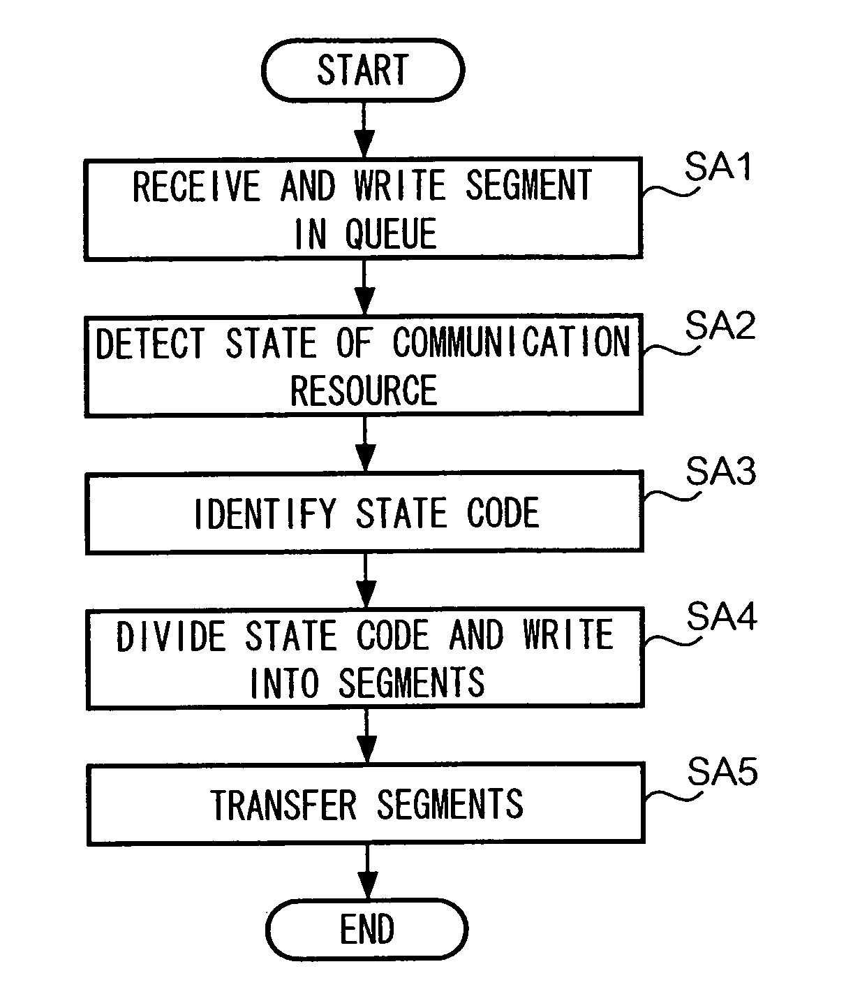
[0011]Specifically, the present invention provides a communication control method comprising notifying by a relay device a transmitter device of a detected state of a communication resource used by the relay device when relaying via the relay device one or more data blocks transmitted from the transmitter device to a receiver device; and increasing or reducing at the transmitter device a number of data blocks transmitted in succession based on the notified state of the communication resource. Preferably, the notifying step includes generating state data showing the detected state of the communication resource; and transmitting the state data to the transmitter device by writing the state data into at least one of the one or more data blocks or one or more acknowledgement data blocks for acknowledging receipt of the one or more data blocks, so that the state data is received by the transmitter device.
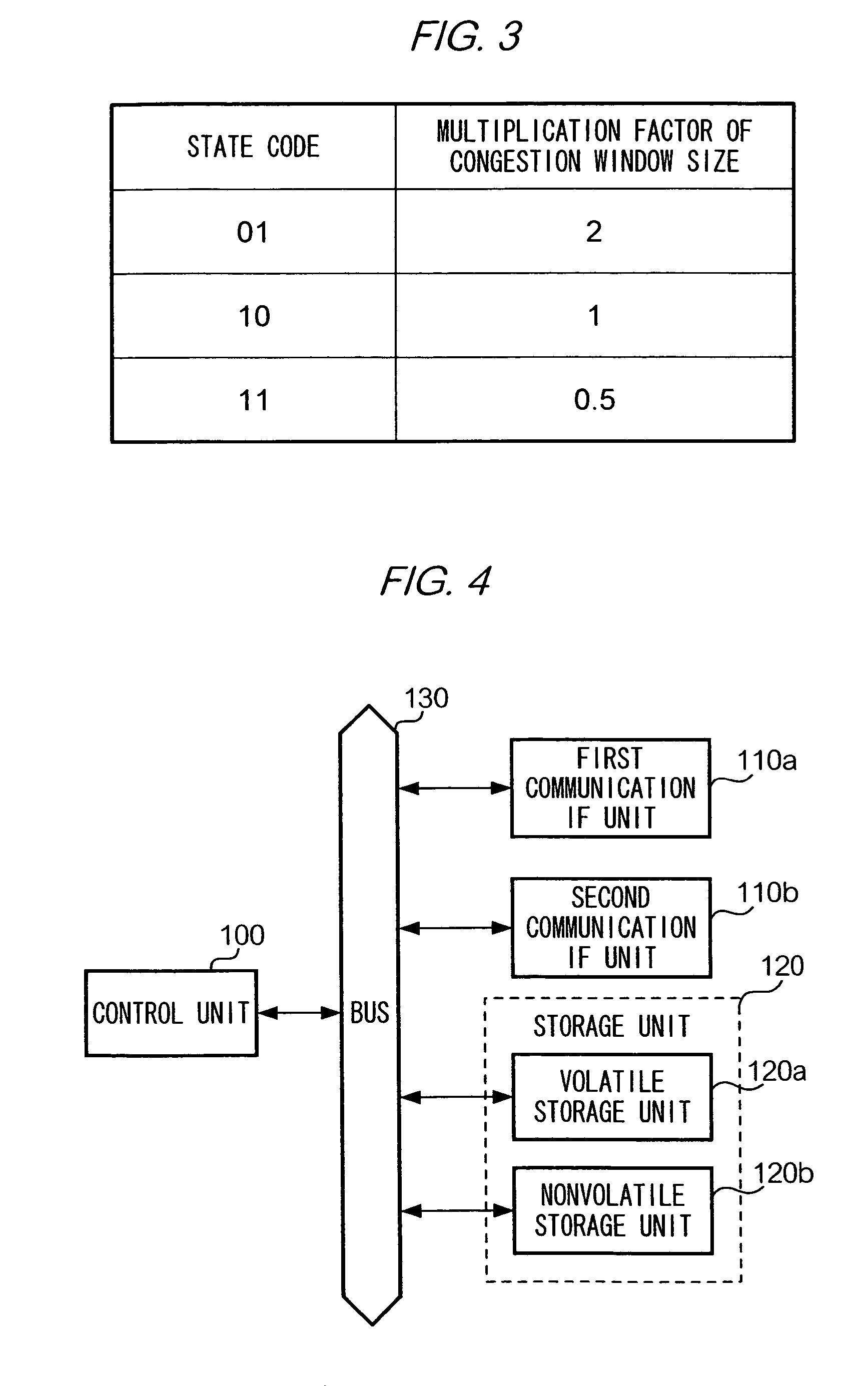
[0015]Preferably, the transmitter device is further provided with storage means for storing at least two instruction data for increasing or reducing the certain number of data blocks, the at least two instruction data being correlated with at least two state data, respectively, wherein the changing means identifies one instruction data, from among the at least two instruction data, that corresponds to the state data received from the relay device, and increases or reduces the number of data blocks according to the identified instruction data. In another preferred embodiment, the transmitter device is further provided with obtaining means for obtaining the state data from the more than one acknowledgement data blocks when the receiving means receives the state data that has been divided and written in more than one acknowledgement data blocks for acknowledging receipt by the receiver device of the certain number of data blocks.
[0017]According to the present invention, efficient data transmission is enabled while avoiding congestion at a relay device. The present invention enables a transmitter device not only to reduce but to increase a number of data blocks transmitted in succession based on a state of a communication resource used by a relay device when transferring a data block transmitted from the transmitter device to a receiver device, while maintaining compatibility with an existing communication protocol.

Problems solved by technology

However, the ECN technique suffers from a drawback in that a value of a CE bit used for notifying a transmitter device of an available capacity of a queue for enabling the transmitter device to change a current size of a congestion window can be set to only “0” or “1”.
Consequently, use of the CE bit in ECN is limited in that it is not possible to signify states of a variety of communication resources used by a relay device in a communication system, each of which communication resources utilizes the CE bit.
However, a problem arises in making such modifications in that downward compatibility in devices utilizing an existing communication protocol may not be available.

Method used


Image

  • Communication control method and system
  • Communication control method and system
  • Communication control method and system

Examples


modification 1

[0079]

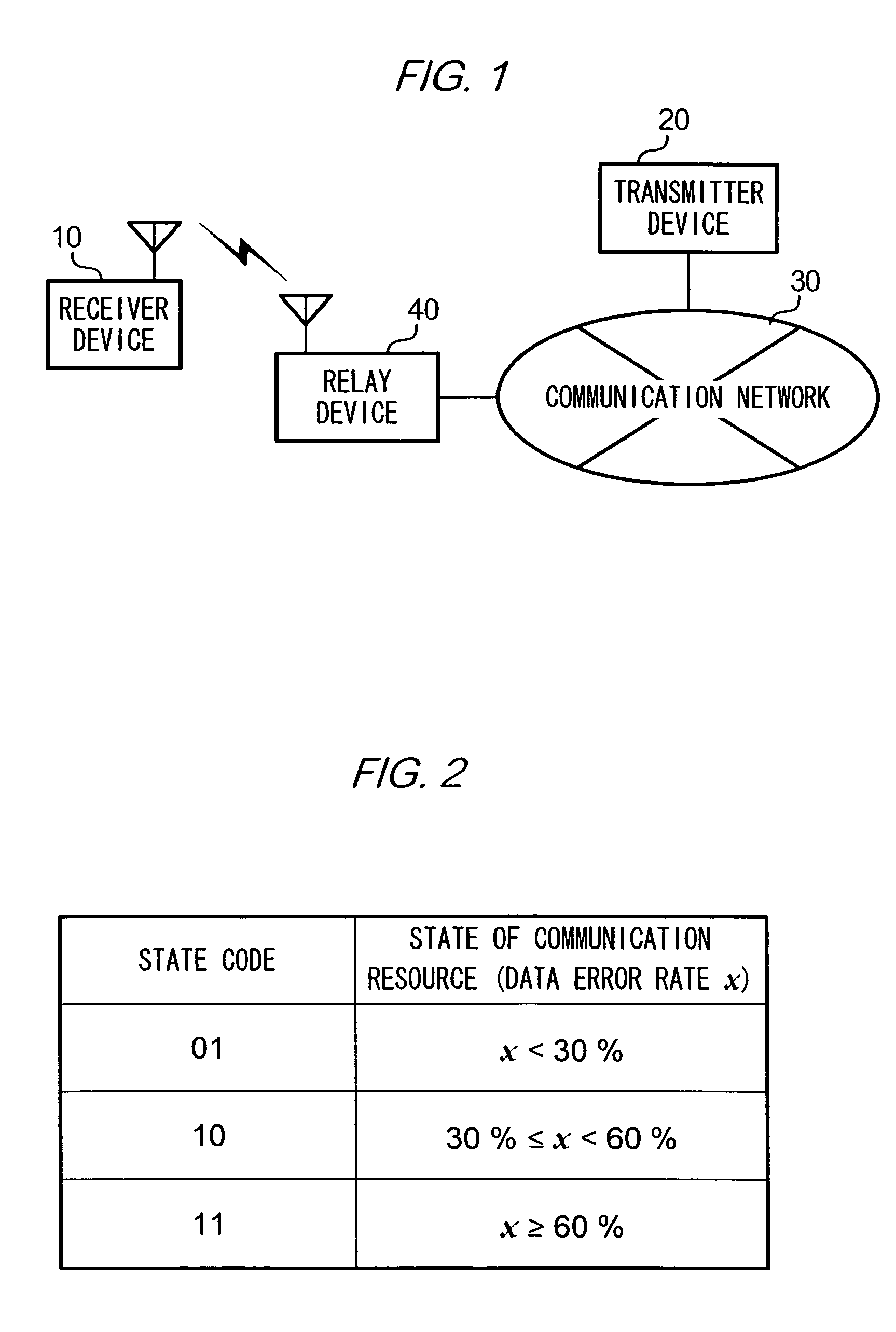
[0080]In the above main embodiment, relay device 40 is a wireless access point device connected to communication network 30 and relays communication between a receiver device 10 located in a wireless area covered by the relay device and a transmitter device 20 connected to communication network 30. However, the relay device according to the present invention is not limited to such a wireless access point device, and may be any relay device that relays communication between a transmitter device and a receiver device, regardless of whether a connection between the relay device and the transmitter or receiver device is wired or wireless. For example, a relay device may be wirelessly connected to both a transmitter and a receiver device, where such a relay device receives segments wirelessly transmitted from the transmitter device and wirelessly transmits the received segments to the receiver device. Also, a relay device may be wired to a first communication network and a second c...

modification 2

[0081]

[0082]In the above main embodiment, a transmitter device, a relay device, and a receiver device perform communication according to TCP. However, a different communication protocol but TCP may be used for performing the communication between the transmitter device and the relay device according to the present invention if a state of a communication resource detected by a relay device can be notified to a transmitter device using the protocol.

[0083]In the above embodiment, receiver device 10 is provided with a functionality of returning an acknowledgement containing data identical to that written in a predetermined area of a received segment. However, even when a receiver device is not provided with such functionality, a state of a communication resource detected by a relay device can still be notified to a transmitter device. Specifically, a relay device is first caused to transfer a segment received from a transmitter device to a receiver device without adding any information....

modification 3

[0084]

[0085]In the above main embodiment, the congestion window size is updated only on the basis of a state of a communication resource. However, in addition to a state of a communication resource, the congestion window size may be updated when predetermined, additional conditions stored in a relay device are fulfilled. For example, only a particular transmitter device may be caused to change the congestion window size. This is enabled by setting in the above predetermined conditions data uniquely identifying a transmitter device that is caused to change the congestion window size based on a state of a communication resource, such as a communication address assigned to the transmitter device or data showing a subnetwork to which the transmitter device belongs. In another example, data showing a particular time zone may be set in the above condition data, and the congestion window size may be caused to be updated only during a designated time.


PUM


Abstract

A relay device 40, when it relays data blocks transmitted in succession from a transmitter device 20 to a receiver device 10, is caused to identify a state code showing a state of a communication resource used when the data blocks are transferred. Relay device 40 divides the identified state code into portions of a predetermined data size and writes the divided portions into a predetermined area of the data blocks. Receiver device 10 transmits to transmitter device 20 an acknowledgement containing the same data as is written in a predetermined area of the received data block. Transmitter device 20, upon receipt of the acknowledgement, reads the state code that is divided and written in the acknowledgement and increases or reduces the number of data blocks on the basis of the state code.

Description

[0001]This application claims priority under 35 U.S.C. §119 to Japanese Patent Application No. 2003-207601 filed Aug. 14, 2003, the entire content of which is hereby incorporated by reference.[0002]1. Technical Field[0003]This invention relates to a technique used for data communication performed via a relay device.[0004]2. Background Information[0005]TCP (Transmission Control Protocol) is a communication protocol used under the OSI (Open Systems Interconnection) Reference Model, and is designed to ensure reliable data communication. Communication under TCP is conducted by dividing data for transmission into data blocks of a predetermined size (hereinafter, “segment”). Each segment has a header, and the header is assigned a unique sequence number which identifies the segment. Header sequence numbers are used to indicate segment transmission order between a transmitter and a receiver device. Consequently, segment loss can be detected at the receiver device on the basis of sequence nu...

Claims


Application Information

Patent Timeline
Patent Type & Authority Patents(United States)
IPC IPC(8): G01R31/08H04L12/66H04L47/27H04L47/43
CPCH04L47/10
Inventor MIYAKE, MOTOHARUINAMURA, HIROSHITAKAHASHI, OSAMU
Owner NTT DOCOMO INC
Learn More