
Low compressive force, non-silicone, high thermal conducting formulation for thermal interface material and package

a technology of thermal interface material and low compressive force, which is applied in the direction of semiconductor devices, semiconductor device details, chemistry apparatus and processes, etc., can solve the problems of reworkability of parts, low thermal conductivity of such materials, and silicone oil based thermal interface materials (tim) in microelectronics

Active Publication Date: 2010-10-19
IBM CORP
View PDF33 Cites 42 Cited by
  • Summary
  • Abstract
  • Description
  • Claims
  • Application Information

AI Technical Summary

Benefits of technology

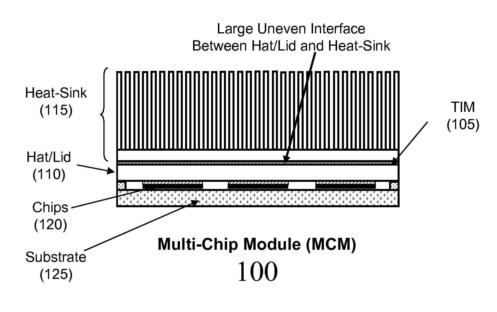
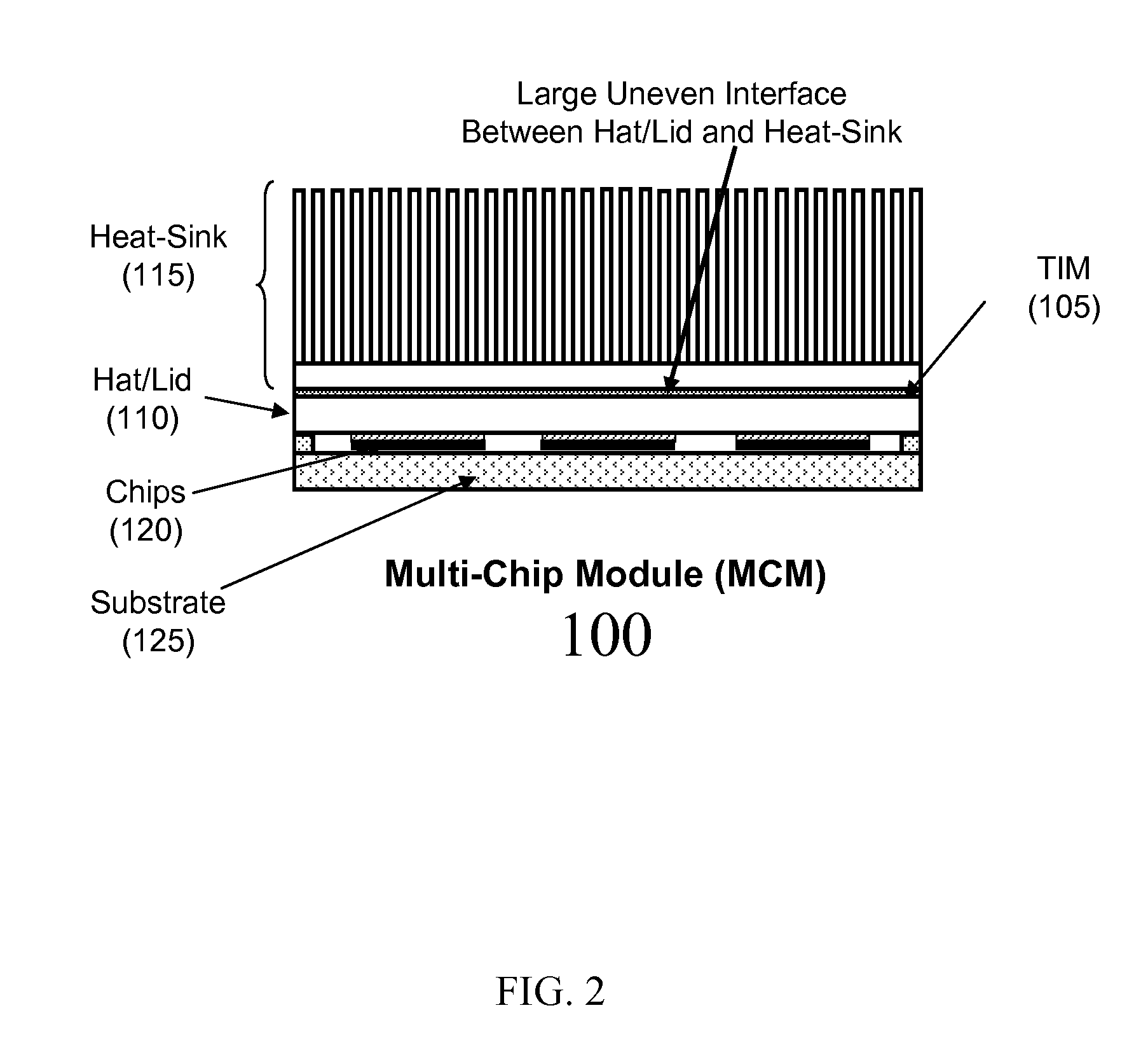
The invention is about a thermal interface material that is used to improve heat transfer between a chip and a heat-sink. The material is made up of non-silicone organics that have high thermal conductivity and a compressive bond-line thickness of less than 100 microns. The material can be made with a compressive force of less than 100 psi. The non-silicone organics can include aluminum particles and aluminum oxide particles. The material can be used in a structure where a hat / lid is placed over a chip and a heat-sink is placed over the hat / lid, with the material in between. The invention provides better heat transfer between the chip and the heat-sink, which can improve the performance of electronic devices.

Problems solved by technology

However, the thermal conductivity of such materials is still very low compared to metals.
Use of silicone oil based thermal interface materials (TIM) in microelectronics packaging could pose challenges with re-workability of parts, e.g., chips, substrates, lid and other hardware due to cross contamination by silicone oil from the TIM.
But, as the filler content in the formulation is increased, the paste becomes more and more stiff or rigid and it becomes difficult to compress the paste to smaller bond-line thickness.
It is often found that the fugitive solvent is a relatively volatile liquid that is difficult to contain for longer periods of time, and can reduce the shelf-life of the TIM.

Method used


Image

  • Low compressive force, non-silicone, high thermal conducting formulation for thermal interface material and package
  • Low compressive force, non-silicone, high thermal conducting formulation for thermal interface material and package
  • Low compressive force, non-silicone, high thermal conducting formulation for thermal interface material and package

Examples


Embodiment Construction

[0018]The present invention generally relates to improved interface materials for semiconductor devices and, more particularly, to low compressive force, non-silicone, high thermal conducting formulation interface material. In implementation, the present invention provides a structure to improve thermal performance, reliability and ease of field rework / repair of devices and / or components with large uneven thermal interfaces. In embodiments, the invention includes thermal interface material that can be located between large thermal interfaces. The thermal interface material has the ability to evenly fill uneven gaps at low compressive force, and also has easy re-workability. In more specific embodiments, the thermal interface material is non-silicone, non-solvent based, which exhibits a high thermal conductivity and longer shelf-life in the field than conventional pastes or materials.

[0019]Advantageously, the use of a non-silicone based thermal interface material of the present inven...


PUM

PropertyMeasurementUnit
thicknessaaaaaaaaaa
particle sizeaaaaaaaaaa

Abstract

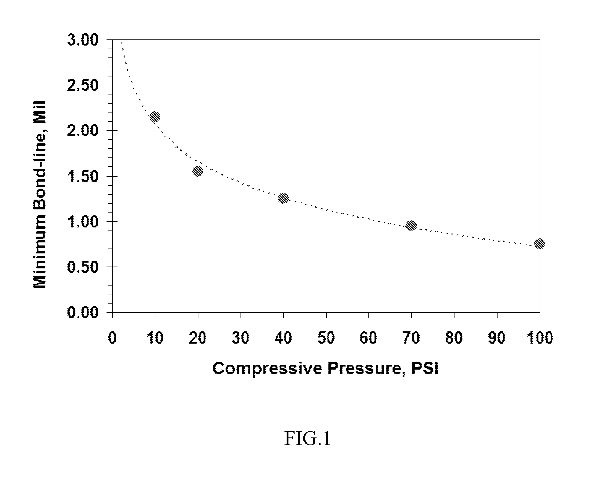
An improved thermal interface material for semiconductor devices is provided. More particularly, low compressive force, non-silicone, high thermal conductivity formulations for thermal interface material is provided. The thermal interface material comprises a composition of non-silicone organics exhibiting thermal conductivity of approximately 5.5 W / mK or greater and a compressed bond-line thickness of approximately 100 microns or less using a compressive force of approximately 100 psi or less.

Description

FIELD OF THE INVENTION[0001]The present invention generally relates to improved thermal interface materials for semiconductor devices and, more particularly, to low compressive force, non-silicone, high thermal conductivity formulation for thermal interface material.BACKGROUND OF THE INVENTION[0002]Heat dissipation is a major factor in the design of semiconductor devices such as analog and power transistors and especially in high performance digital switching circuits formed at high integration density. It has become the practice to incorporate attachment of a heat sink or other heat removal structure (e.g. a liquid-cooled cold plate) into the design and manufacturing of integrated circuit packages since heat removal is critical to both performance and reliability of the integrated circuits.[0003]For attachment of heat sinks to integrated circuit packages, it has been the practice to use an adhesive which has a relatively good thermal conductivity. However, the thermal conductivity ...

Claims


Application Information

Patent Timeline
Patent Type & Authority Patents(United States)
IPC IPC(8): H01L23/10
CPCH01L23/3737H01L2924/0002H01L2924/00H01L23/18H01L23/373
Inventor IRUVANTI, SUSHUMNAKEMINK, RANDALL G.KUMAR, RAJNEESHOSTRANDER, STEVEN P.SINGH, PRABJIT
Owner IBM CORP
Learn More