Pressure suppression and decontamination apparatus and method for reactor container

a technology of pressure suppression and decontamination apparatus, which is applied in the direction of nuclear engineering problems, greenhouse gas reduction, nuclear elements, etc., can solve the problems of large amount of radioactive substances, melt of reactor core, etc., to suppress the pressure rise in the reactor container and suppress the density increase of radioactive substances

Inactive Publication Date: 2010-10-12
KK TOSHIBA
View PDF20 Cites 0 Cited by
  • Summary
  • Abstract
  • Description
  • Claims
  • Application Information

AI Technical Summary

Benefits of technology

[0010]Accordingly, an object of this invention is to provide an apparatus and a method for pressure suppression and decontamination for a reactor container which can suppress the pressure rise in the reactor container and can suppress the density increase of radioactive substances, at an emergency case such as troubles with the coolant system for the reactor.
[0013]According to the present invention, it is possible to provide an apparatus and a method for pressure suppression and decontamination for a reactor container which can suppress the pressure rise in the reactor container and can suppress the density increase of radioactive substances, at an emergency case such as troubles with the coolant system for the reactor.

Problems solved by technology

When a severe trouble such as a trouble with a coolant system takes place in a nuclear reactor, it is possible that the reactor core melts, breaks through the bottom panel board of the reactor pressure vessel and falls into a bottom dry well.
At that time, it is possible that a great amount of radioactive substances are generated and non-condensable gas such as hydrogen that is generated through reactions of metal and water fills up in the reactor container and causes a pressure rise in the reactor container.

Method used


Image

  • Pressure suppression and decontamination apparatus and method for reactor container
  • Pressure suppression and decontamination apparatus and method for reactor container
  • Pressure suppression and decontamination apparatus and method for reactor container

Examples


first embodiment

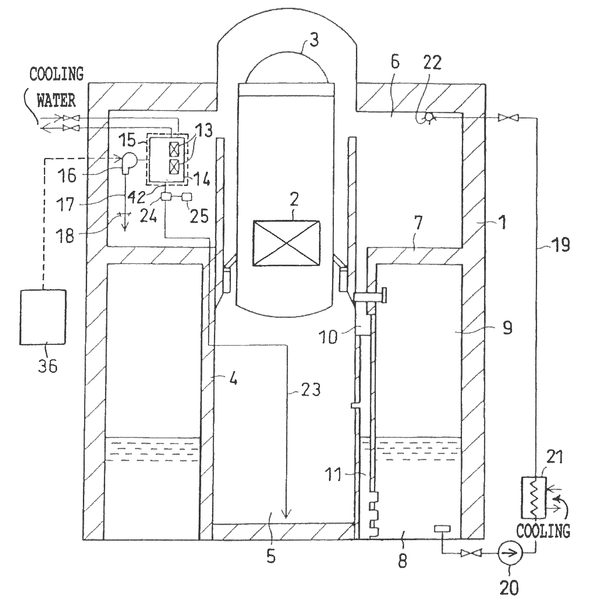
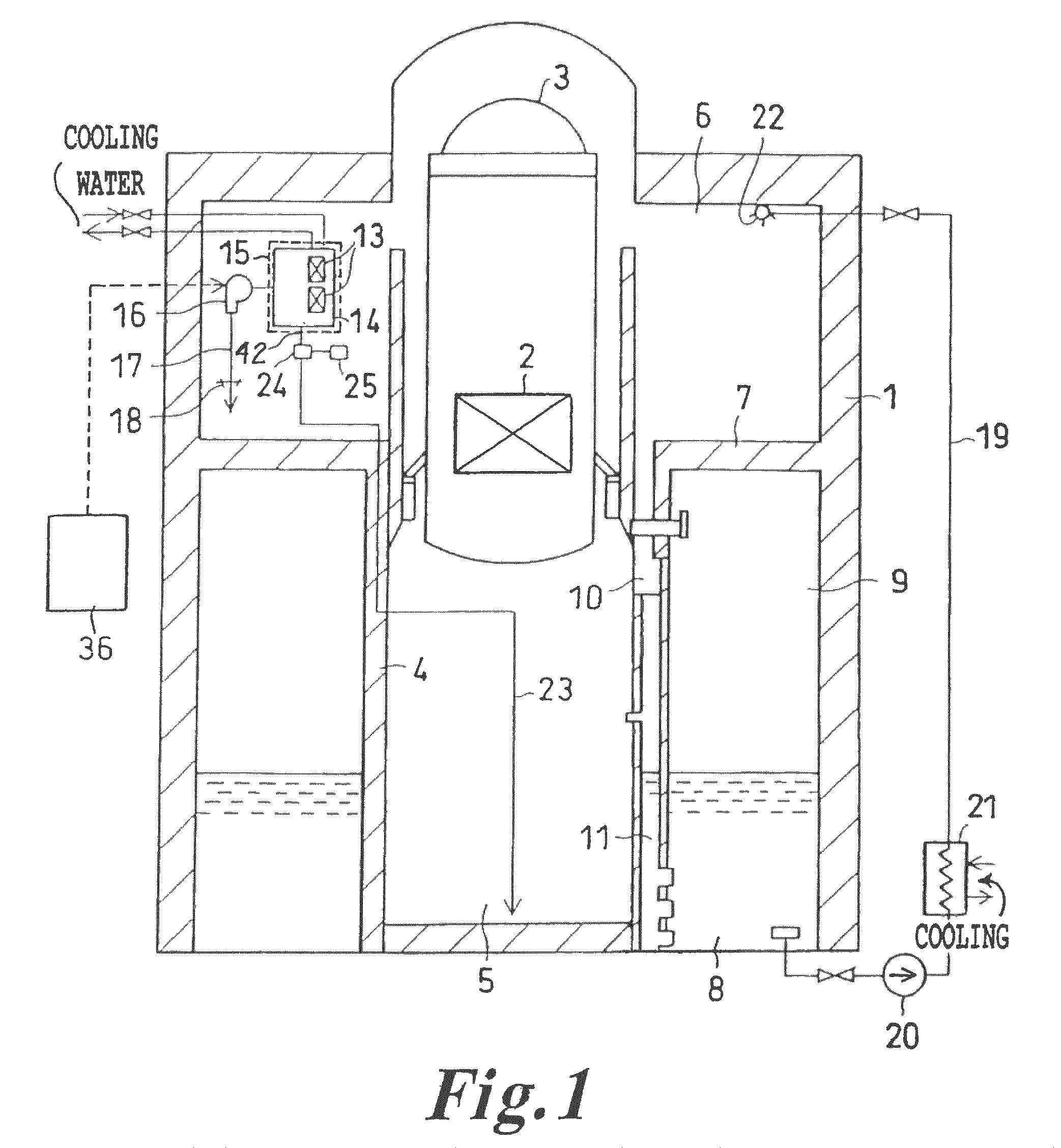
[0024]FIG. 1 is a cross section drawing showing a reactor container provided with a pressure suppression and decontamination apparatus for a reactor container according to a first embodiment of this invention.

[0025]In a reactor container 1, a reactor pressure vessel 3 containing a reactor core 2 for holding nuclear fuel is supported by means of pedestals 4. Also, a bottom dry well 5 surrounded by the pedestals 4, a top dry well 6 surrounding the reactor pressure vessel 3 and a pressure suppressing room 9, which is partitioned by a diaphragm floor 7 below the top dry well 6 and contains a pressure suppressing pool water 8 inside are provided in the reactor container 1.

[0026]The top dry well 6 and the bottom dry well 5 are communicated hydraulically by means of a communicating canal 10. The both dry wells 5 and 6 and a pressure suppressing room 9 are connected each other by a vent tube 11 which extends into the pressure suppressing pool water 8. It is so constructed that the pressure ...

second embodiment

[0040]FIG. 7 is a cross section drawing showing a reactor container provided with a pressure suppression and decontamination apparatus for a reactor container according to a second embodiment of this invention.

[0041]As shown in FIG. 7, this embodiment provides the construction that the change over device 24 and the sprinkling device 25 are provided in the bottom dry well 5. The respective constructions of the dry well cooling unit 15, the changeover device 24 and the sprinkling device 25 are the same as shown in the first embodiment. According to this embodiment, the radioactive substances can be removed efficiently at a range where the density of the radioactive substances is high.

[0042]Meantime, it should be understood that the present invention is not limited to the embodiments described in the above. For example, when the embodiment of the present invention is described, a boiling water reactor (BWR) is taken as an example as shown in FIG. 1 and FIG. 7. But this invention can be...


PUM


Abstract

A pressure suppression and decontamination apparatus for a reactor container which is provided with a reactor pressure vessel containing nuclear core fuel and forms a dry well space including, a dry well cooling unit for cooling a gas in the dry well space and for producing a condensate of the gas, a circulation device for leading the gas in the dry well space to the dry well cooling unit, and a sprinkling device for sprinkling the condensate in the dry well space.

Description

CROSS-REFERENCE TO RELATED APPLICATIONS[0001]This application is based upon and claims the benefit of priority from the prior Japanese Patent Application No. 2004-92318, filed on Mar. 26, 2004; the entire contents of which are incorporated herein by reference.BACKGROUND OF THE INVENTION[0002]1. Field of the Invention[0003]The present invention relates to an apparatus and a method for pressure suppression and decontamination for a reactor container, and more particularly to an apparatus and a method for pressure suppression and decontamination for a reactor container which cools the inside of reactor container and suppresses the pressure rise and the density increase of radioactive substances, at an emergency case such as troubles with the coolant system for the reactor.[0004]2. Description of the Background[0005]When a severe trouble such as a trouble with a coolant system takes place in a nuclear reactor, it is possible that the reactor core melts, breaks through the bottom panel b...

Claims


Application Information

Patent Timeline
Patent Type & Authority Patents(United States)
IPC IPC(8): G21C9/00G21C9/004G21C9/012G21C15/18G21F9/02
CPCG21C9/004G21C15/18G21Y2002/501G21Y2004/20G21Y2004/30G21Y2004/40Y02E30/40Y02E30/30
Inventor TOBIMATSU, TOSHIMIYOKOBORI, SEIICHIAKINAGA, MAKOTO
Owner KK TOSHIBA
Why Eureka
Try Eureka