
Biometric information input device, biometric authentication device, biometric information processing method, and computer-readable recording medium recording biometric information processing program

a biometric information and authentication technology, applied in computing, instruments, agriculture tools and machines, etc., can solve the problems of rotational displacement exceeding the acceptable range of matching methods, authentication failing, and sometimes failing authentication, and achieve high convenience, reliable results, and reduced manufacturing costs

Inactive Publication Date: 2010-10-05
FUJITSU LTD
View PDF29 Cites 44 Cited by
  • Summary
  • Abstract
  • Description
  • Claims
  • Application Information

AI Technical Summary

Benefits of technology

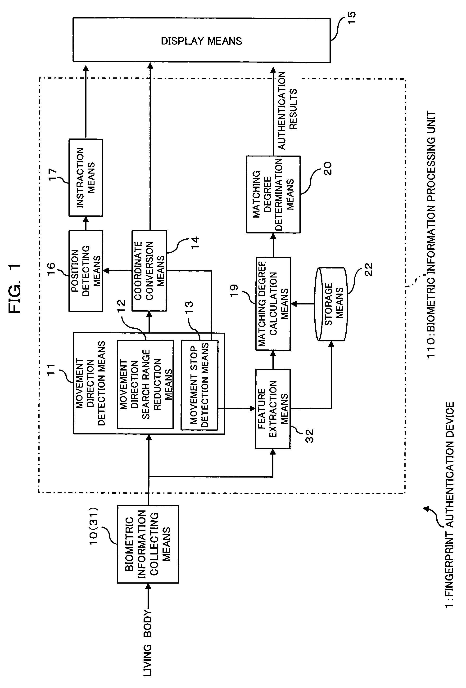
[0027]Note that the device may include movement direction search range reduction means for, when the same movement direction has been successively detected by the movement direction detection means, reducing a movement direction search range defined as a range over which the movement direction detection means detects the movement direction to a predetermined range including the detected movement direction.
[0049]Further, the degree of freedom of the mounting direction of the biometric information collection means can be made high and reduction in the mounting area of a wiring pattern leads to reduction in the volume and price of the device.

Problems solved by technology

For biometric authentication, biometric information that is common to all persons and consistent throughout the lifetime of a person (e.g., fingerprint, palm print, finger vein, palm vein, etc.) is used, but there are problematic situations in which authentication fails due to various factors.
Further, conventionally, a variety of methods for matching biometric information have been put into practice, however, in some of those methods, authentication sometimes fails due to rotational displacement of biometric information.
That is, when the degree of freedom which is of the rotation of a living body relative to a biometric information input device, or vice versa, is large, rotational displacement exceeds an acceptable range for a matching method and false rejection rate increases.
Moreover, although a method for repeating matching while rotating matching data or enrollment data, in order to accommodate the degree of freedom in the rotational direction, has been also known, rotating the matching data or enrollment data sometimes causes matching data and enrollment data corresponding to different persons to accidentally match, leading to an increase in false acceptance rate.
However, in such a conventional information processing device, when a fingerprint image is input using a sweep fingerprint sensor, the device has to cause a finger to slide in the previously expected direction and therefore needs to rotate itself to read a fingerprint, thereby disadvantageously increasing the degree of complexity.
However, the sensor needs to acquire the partial images in a shorter time interval so that the images are overlapped one another even when a finger slides quickly, which imposes a heavy load on the sensor to detect the slide direction.
Therefore, there is also a problematic situation in which the sensor needs to efficiently detect the slide direction.
However, even such biometric information could not cause a person to be identified as the person himself / herself in the event where different sites are input when enrolled and matched.
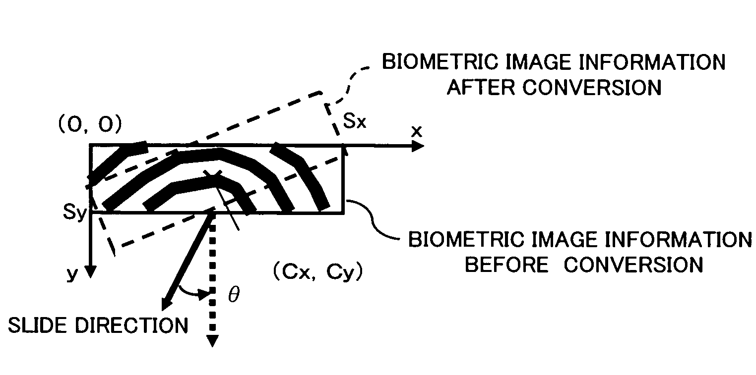
However, in a device tailored to be used, oriented in an up / down or left / right direction, biometric information image to be input is displaced in the rotational direction, potentially preventing the user from viewing, for confirmation, the image information.

Method used


Image

  • Biometric information input device, biometric authentication device, biometric information processing method, and computer-readable recording medium recording biometric information processing program
  • Biometric information input device, biometric authentication device, biometric information processing method, and computer-readable recording medium recording biometric information processing program
  • Biometric information input device, biometric authentication device, biometric information processing method, and computer-readable recording medium recording biometric information processing program

Examples


first modification

(B) Explanation of First Modification

[0220]FIG. 18 is a block diagram illustrating the functional configuration of a first modification of the fingerprint authentication device as one embodiment of the invention.

[0221]A fingerprint authentication device 101 is configured in nearly the same way as in the first embodiment, except that a biometric information central position detection means 21 is provided instead of the position detection means 16 in the fingerprint authentication device 1 of the first embodiment. Note that in FIG. 18, the same numerals previously used designate the same or nearly the same elements and therefore detailed explanation thereof is omitted.

[0222]The biometric information central position detection means 21 is for detecting a central position of a partial fingerprint image (biometric information) collected by the fingerprint sensor 31 (biometric information collection means 10). Note that as a method for detecting the central position of partial image throu...

second modification

(C) Explanation of Second Modification

[0230]For an information processing device provided with the above-described fingerprint sensor 31 and display 81, it could be proposed to move a cursor (pointer) displayed on the display 81 using the fingerprint sensor 31. That is, the fingerprint sensor 31 is allowed to function as a pointing device.

[0231]FIG. 19 is a block diagram illustrating the functional configuration of a second modification of the fingerprint authentication device as one embodiment of the invention. As shown in FIG. 19, a fingerprint authentication device 102 of the second modification includes the biometric information collection means 10, the movement direction detection means 11, the coordinate conversion means 14, the display means 15, the storage means 22, the biometric information movement direction correction means 40 (reference direction setting means 41), a movement distance detection means 42, and a pointer movement control means 43. Note that in FIG. 19, the ...

application examples

(D) Application Examples

[0248]Examples of applications of the fingerprint authentication device of the invention will be shown below.

[0249](1) Mobile Phone

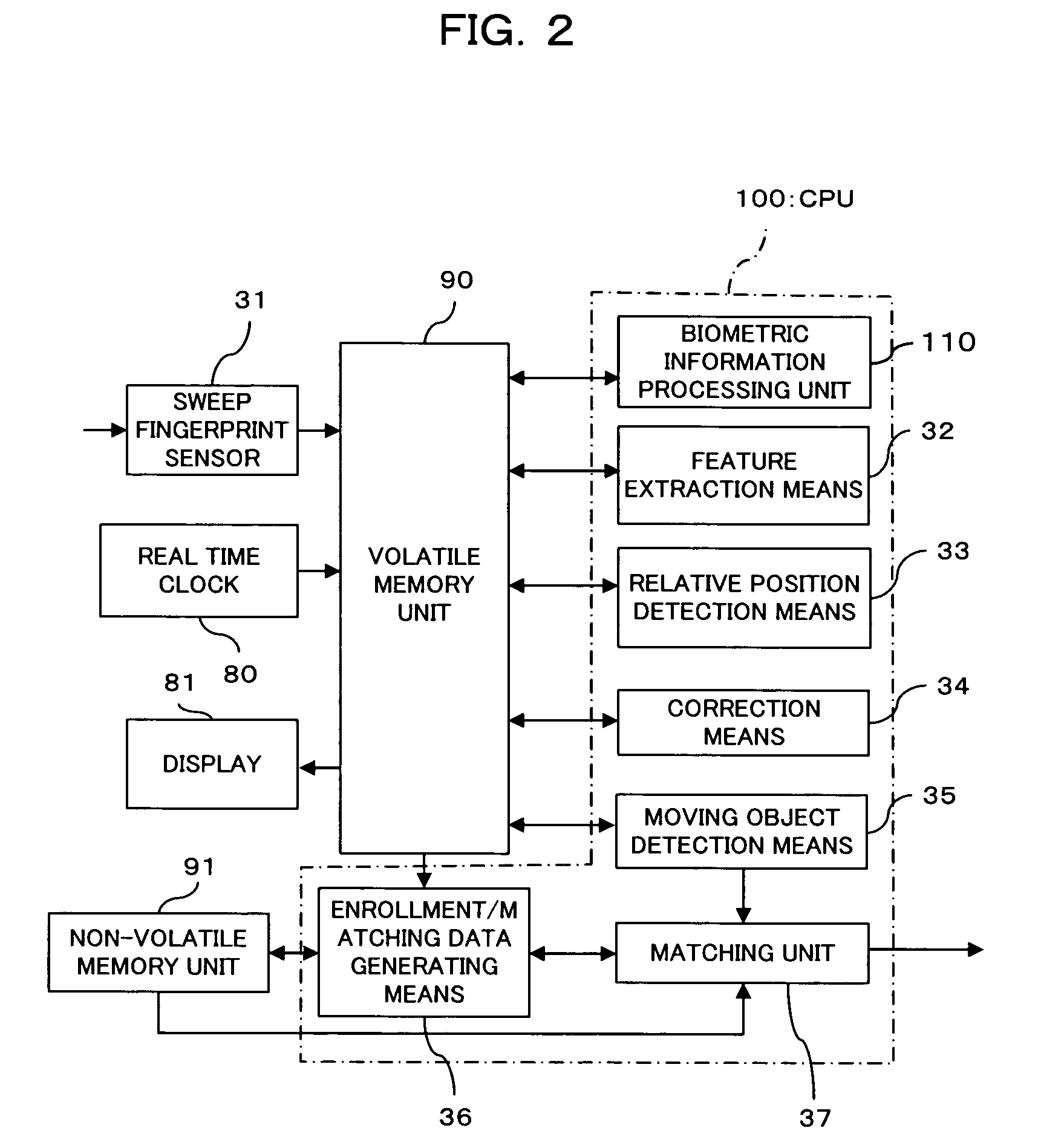
[0250]FIGS. 23(a), 23(b), 23(c) are diagrams illustrating examples in which the fingerprint authentication device of the invention is applied to a mobile device (mobile phone) 200 provided with a sweep fingerprint sensor and FIGS. 24(a), 24(b) are diagrams illustrating examples of fingerprint images derived from images collected in the states of FIGS. 23(b), 23(c).

[0251]The mobile device 200 shown in FIGS. 23(a) to 23(c) incorporates a sweep fingerprint sensor 31 therein for the purpose of inclusion of functions such as owner authentication. As a mobile device such as a recent mobile phone is reduced in volume, how a user holds the device changes in various forms. Particularly, since the user holds the mobile phone by one hand, how the user holds the phone is considered to easily change. At the time of enrollment, the user was unf...


PUM


Abstract

The invention is a biometric information input device including biometric information collection means for reading a relatively-moving living body site and successively collecting a plurality of partial images of the living body site as biometric information, movement direction detection means for detecting a movement direction of the living body site with respect to the biometric information collection means based on the biometric information collected by the biometric information collection means, and coordinate conversion means for performing a coordinate conversion on the biometric information collected by the biometric information collection means using the movement direction detected by the movement direction detection means, thereby allowing the device to be used irrespective of a direction in which a living body is swept when biometric information is entered.

Description

BACKGROUND OF THE INVENTION[0001]1. Field of the Invention[0002]The present invention relates to a technology for processing biometric information input for authentication, and particularly to a method for partially and successively collecting biometric information.[0003]2. Description of the Related Art[0004]In a common biometric authentication device, biometric data (enrollment data) is previously prepared (recorded) from biometric information and further biometric data (matching data) is created from biometric information to be authenticated, and then, the matching data is compared to the enrollment data for authentication.[0005]For biometric authentication, biometric information that is common to all persons and consistent throughout the lifetime of a person (e.g., fingerprint, palm print, finger vein, palm vein, etc.) is used, but there are problematic situations in which authentication fails due to various factors.[0006]Further, such authentication failures can be grouped into...

Claims


Application Information

Patent Timeline
Patent Type & Authority Patents(United States)
IPC IPC(8): G06K9/00
CPCG06F3/03547G06K9/00026G06F2203/0338G06V40/1335A01D34/54A01D34/47A01D34/62
Inventor ABIKO, YUKIHIROSHINZAKI, TAKASHI
Owner FUJITSU LTD
Learn More