
Manufacturing apparatus of plugged honeycomb structure and manufacturing method of the same

a manufacturing method and honeycomb technology, applied in the direction of turning machine accessories, turning tools, buttons, etc., can solve the problems of increased cost, increased labor and time, and difficulty in obtaining uniform plugging depth, so as to improve the use ratio of plugging material, reduce the amount of plugging material for use, and easy to be peeled later

Active Publication Date: 2010-10-05
NGK INSULATORS LTD
View PDF18 Cites 32 Cited by
  • Summary
  • Abstract
  • Description
  • Claims
  • Application Information

AI Technical Summary

Benefits of technology

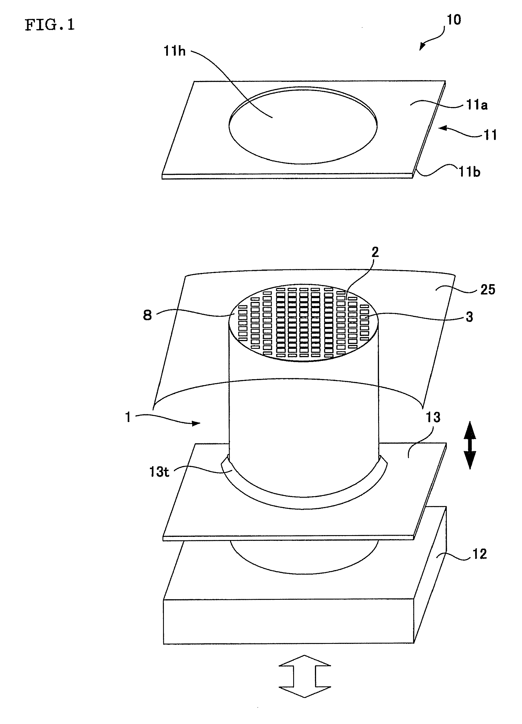
The present invention provides a manufacturing apparatus and method for a plugged honeycomb structure that can shorten the manufacturing time and decrease the manufacturing cost. The apparatus includes a table portion with a through hole and a film holding portion to hold the end of the honeycomb structure in the through hole. The film holding portion fixes the remaining portion of the film covering the end face of the honeycomb structure on the side of the second face of the table portion. A plugging material is then supplied and filled into the cells of the honeycomb structure. The apparatus and method can provide a faster and more cost-effective way to manufacture plugged honeycomb structures.

Problems solved by technology

However, according to the above method of making the holes in the adhesive sheet and immersing, into the slurry, the honeycomb structure provided with this adhesive sheet as the mask, an operation time is required for leveling the slurry for the immersion, which factors into cost increases.
Moreover, the leveling is a very delicate step, the outer peripheral portion of the structure thickens or thins owing to even slight deviation, and it is therefore difficult to obtain a uniform plugging depth.
A leveling precision agrees with a depth precision, and hence additional labor and time are necessary for the leveling step.
Moreover, the film needs to be bent so that the immersed end is not made dirty, but it is not easy to appropriately bend the film.
Moreover, it is not easy to peel the bent film attached to the side surface of the structure after the plugging, which hinders automation steps.

Method used


Image

  • Manufacturing apparatus of plugged honeycomb structure and manufacturing method of the same
  • Manufacturing apparatus of plugged honeycomb structure and manufacturing method of the same
  • Manufacturing apparatus of plugged honeycomb structure and manufacturing method of the same

Examples


examples

[0065]Hereinafter, the present invention will be described in more detail based on examples, but the present invention is not limited to these examples.

[0066]A ceramic material as a main raw material selected from the group consisting of cordierite, mullite, alumina, silicon carbide and a combination of them was blended with water and a binder, dispersed, mixed and kneaded to obtain a formed material. The material was extruded into a columnar shape by a clay kneader, and extrusion-formed by an extrusion forming machine to obtain a honeycomb structure having a cell dimension of 2 mm×2 mm and a pitch of 3 mm.

[0067]Next, a plurality of cells of both end faces of the resultant honeycomb structure were alternately plugged by use of a manufacturing apparatus having a film holding portion 13 described above with reference to FIG. 5 in plugging steps of FIGS. 7A to 7C. The material of the film holding portion 13 was urethane rubber (hardness: 90°), the film holding portion 13 had a height o...


PUM

PropertyMeasurementUnit
thicknessaaaaaaaaaa
heightaaaaaaaaaa
thicknessaaaaaaaaaa

Abstract

A manufacturing apparatus of a plugged honeycomb structure includes a table portion having a through hole into which the end of a honeycomb structure is inserted, positioning means for positioning and holding the honeycomb structure in the through hole of the table portion in such a manner that its end face appears on the side of a first face of the table portion, and a film holding portion fixing the remaining portion of a film on the side of a second face of the table portion. After or before fixing the film, holes corresponding to openings of cells of the honeycomb structure are formed in the film, and a plugging material is filled into the holes, to manufacture the plugged honeycomb structure using the apparatus.

Description

BACKGROUND OF THE INVENTION[0001]1. Field of the Invention[0002]The present invention relates to a manufacturing apparatus of a plugged honeycomb structure for forming plugging portions at opening ends of cells of a honeycomb structure, and a manufacturing method of the same.[0003]2. Description of the Related Art[0004]There is an increasing need to remove, from an exhaust gas, fine particles and harmful substances included in the exhaust gas from an internal combustion engine, a boiler or the like, in consideration of an influence on the environment. In particular, a regulation on the removal of the fine particles (hereinafter sometimes referred to as the particulate matter (PM)) exhausted from a diesel engine tends to be strengthened in Europe, the United States and Japan, and a honeycomb structure is used in a collecting filter for removing the PM.[0005]Examples of the filter used for such a purpose include a honeycomb filter using a plugged honeycomb structure in which a plurali...

Claims


Application Information

Patent Timeline
Patent Type & Authority Patents(United States)
IPC IPC(8): B29C45/14B28B21/54B28C7/16B23K26/36
CPCB01D46/0001B28B11/006B28B11/007B01D2279/30
Inventor TSUJI, HIROYUKIKONDO, YOSHIMASATOKUNAGA, TAKESHIODA, TOSHIOYOSHIDA, SHINYAOGATA, TAKAYUKI
Owner NGK INSULATORS LTD
Learn More