Power electronics assembly with cooling element

a technology of electronic assembly and cooling element, which is applied in the direction of power cables, lighting and heating apparatus, cables, etc., can solve the problems of reduced cycle strength, thermal stress and breakage of the insulating substrate, and increase the risk of assembly breakage, so as to achieve the effect of improving the structur

Inactive Publication Date: 2010-09-21
ECPE ENG CENT FOR POWER ELECTRONICS
View PDF15 Cites 13 Cited by
  • Summary
  • Abstract
  • Description
  • Claims
  • Application Information

AI Technical Summary

Benefits of technology

[0008]That object is attained by a power electronic arrangement comprising an insulating substrate which is provided with one or more metallisation surfaces, a cooling element arranged beneath the insulating substrate and one or more power electronic components which are disposed on one side of the insulating substrate in opposite relationship to the cooling element on the respective metallisation surfaces, wherein disposed on a surface of the insulating substrate is a metal layer portion which projects beyond the insulating substrate at all sides and thus the region of the metal layer portion projecting beyond the insulating substrate forms a metal flange which borders the insulating substrate, wherein the cooling element has one or more openings on its side towards the insulating substrate beneath the insulating substrate and provided beneath the insulating substrate is a cavity delimited by the insulating substrate and wall surfaces of the one or more openings for receiving a liquid cooling agent and the metal flange is connected to the cooling element. The solution according to the invention provides a higher level of cycle strength, a simplification in the sealing arrangement and a more compact structure.
[0010]The metal flange is pressed against the cooling element by means of the clamping frame whereby a force-locking connection and sealing integrity are implemented at the same time. That permits a direct afflux flow against the underside of the insulating substrate by means of the cooling agent, with an enhanced cycle strength. If the insulating layer were clamped directly between the clamping frame and the cooling element, then, in addition to mechanical fixing of the module, the pressing force would thus have to be applied to provide for the necessary sealing integrity against the insulating substrate by way of a seal, which on the one hand would lead to an increased risk of breakage upon assembly and also a reduced cycle strength. The connection between an insulating substrate and a (metallic) cooling device has a high level of static friction by virtue of the oxidised surface of the cooling device, which leads to thermal stress and breakage of the insulating substrate. Those disadvantages are avoided in this solution according to the invention.
[0017]In accordance with a preferred embodiment of the invention the peripherally extending clamping frame overlaps the insulating substrate. That prevents the insulating substrate from breaking in the event of an excessive pressure in respect of the cooling agent. Furthermore it is advantageous if the clamping frame is provided with legs which fix the substrate against an increased pressure not just at the edge. That is advantageous in particular when using ceramic plates of larger surface area as the insulating substrate.
[0018]It can further be provided that the insulating substrate is mounted by way of one or more spacers on the cooling element. In the case of a reduced pressure in respect of the cooling agent, that prevents fracture of the insulating substrate.
[0019]Further advantages are achieved by a bellows configuration or a corrugation being shaped in the metal flange. The bellows configuration or the corrugation is in that case preferably formed in the metal flange between the insulating substrate and the region of the metal flange, by the metal flange being gripped between the sealing surfaces of the clamping frame and of the cooling element. The corrugation or the bellows configuration provides that thermal / mechanical stresses which are caused by the differing coefficients of expansion of the materials used or by an increased pressure or a reduced pressure in respect of the cooling agent are resiliently absorbed. That obviates fracture of the insulating substrate. Furthermore the notch action between the metal flange and the insulating substrate is minimised and that therefore prevents premature detachment of the flange from the insulating substrate.

Problems solved by technology

If the insulating layer were clamped directly between the clamping frame and the cooling element, then, in addition to mechanical fixing of the module, the pressing force would thus have to be applied to provide for the necessary sealing integrity against the insulating substrate by way of a seal, which on the one hand would lead to an increased risk of breakage upon assembly and also a reduced cycle strength.
The connection between an insulating substrate and a (metallic) cooling device has a high level of static friction by virtue of the oxidised surface of the cooling device, which leads to thermal stress and breakage of the insulating substrate.

Method used


Image

  • Power electronics assembly with cooling element
  • Power electronics assembly with cooling element
  • Power electronics assembly with cooling element

Examples


Embodiment Construction

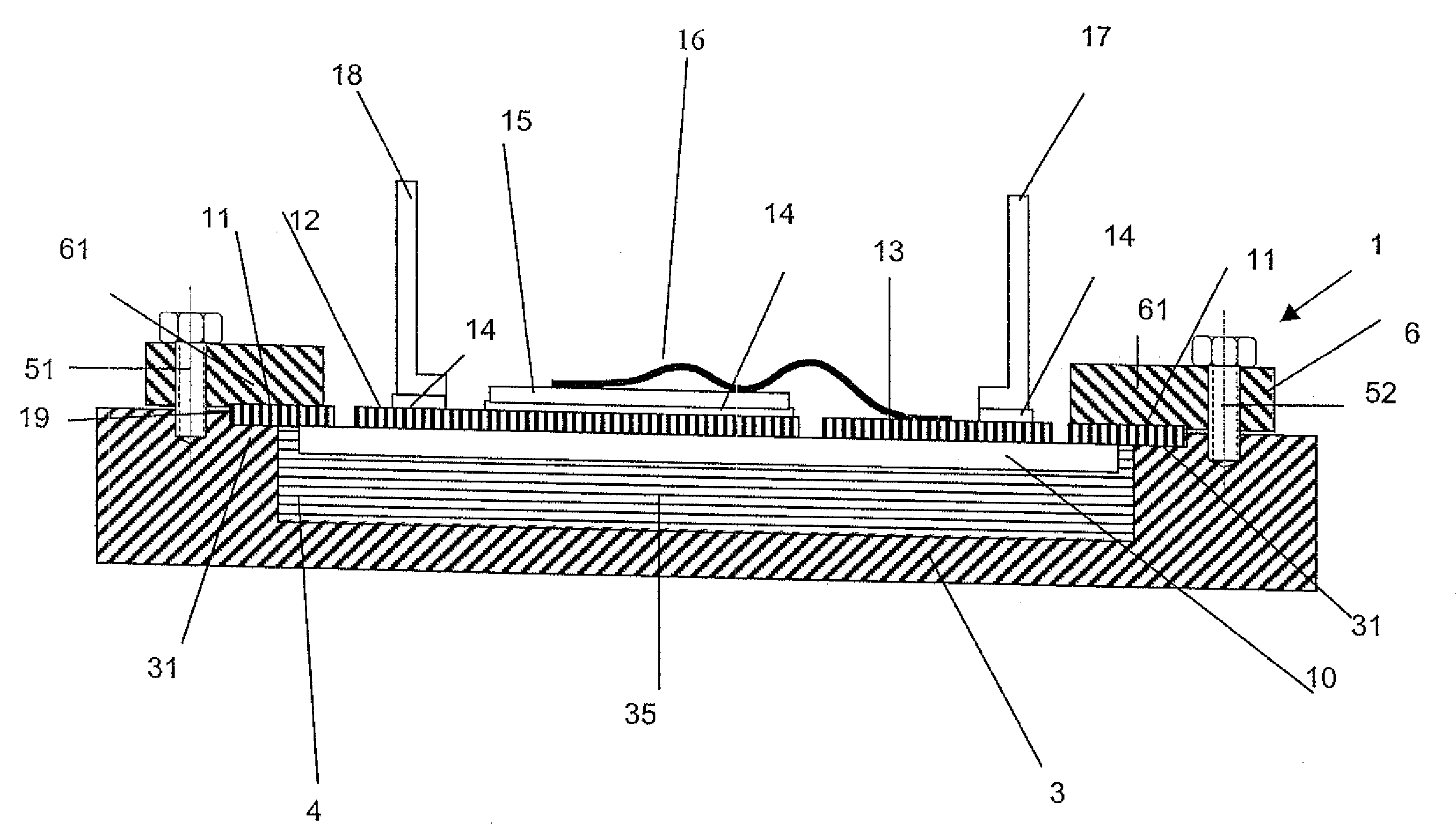
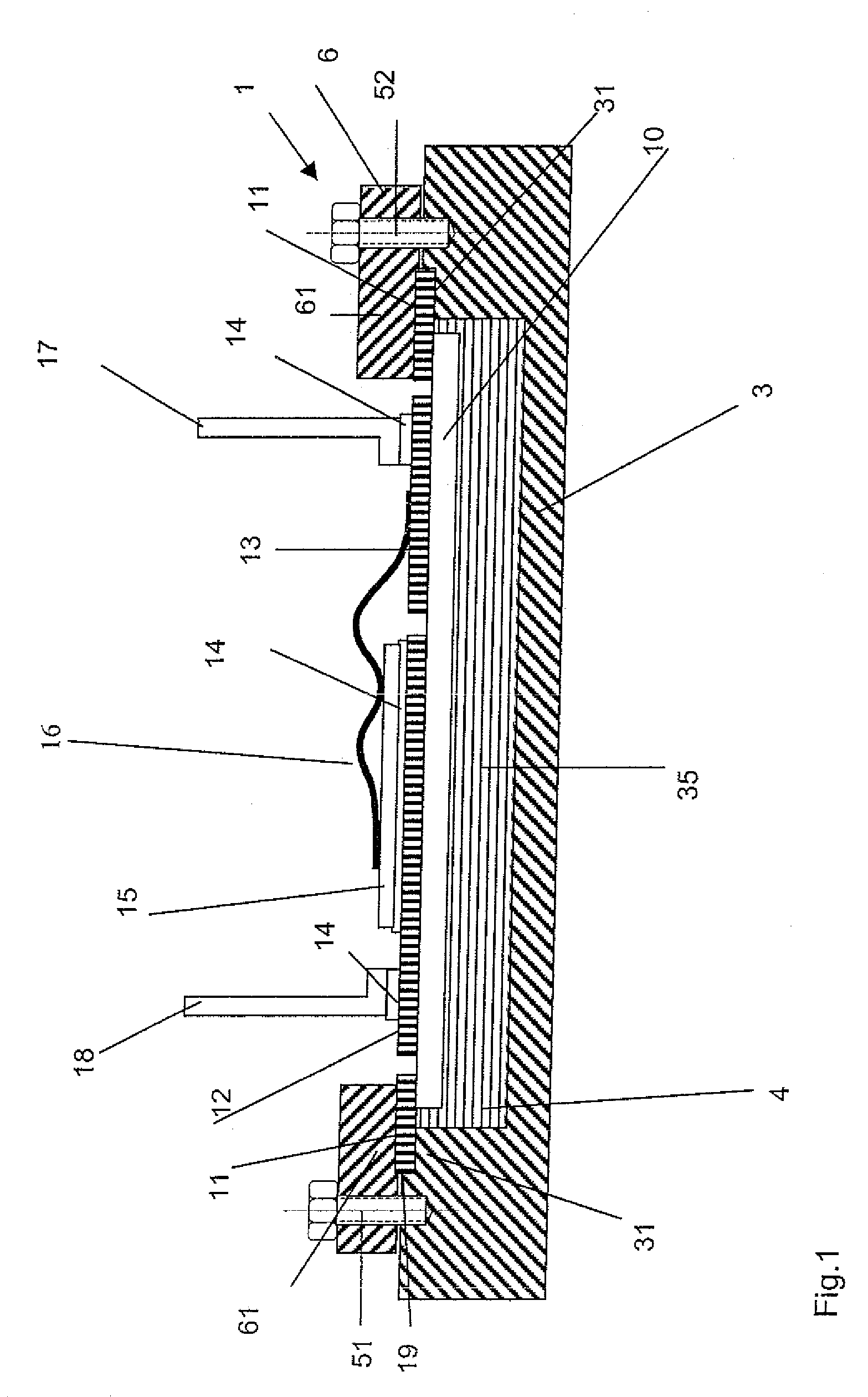
[0026]FIG. 1 shows a power electronic arrangement 1 with a cooling element 3, a clamping frame 6 and an insulating substrate 10.

[0027]The insulating substrate 10 is a ceramic substrate in plate form, the thickness of which is greater than 0.1 millimeter. Preferably the insulating substrate is of a thickness of between 0.2 and 4 millimeter. The insulating ceramic preferably comprises aluminum oxide, aluminum nitride, boron nitride or silicon nitride. It is also possible for the insulating substrate 10 to comprise a plastic material or a plastic material which is filled with ceramic.

[0028]On its top side the insulating substrate 10 is provided with a metal layer portion 19 which is bonded on to the insulating substrate or soft-soldered, actively soldered or brazed or laminated on to the insulating substrate. The metal layer portion 19 forms on the insulating substrate 10 a plurality of metallisation surfaces of which two metallisation surfaces 12 and 13 are shown in FIG. 1. Arranged o...


PUM

PropertyMeasurementUnit
thicknessaaaaaaaaaa
thicknessaaaaaaaaaa
thicknessaaaaaaaaaa

Abstract

The invention concerns a power electronic arrangement comprising an insulating substrate, a cooling element arranged beneath the insulating substrate and one or more power electronic components disposed on a respective metallization surface of the insulating substrate. Disposed on the surface of the insulating substrate is a metal layer portion which projects beyond the insulating substrate at all sides. The region of the metal layer portion, that projects beyond the insulating substrate, forms a metal flange which borders the insulating substrate. The cooling element, on its side towards the insulating substrate, beneath the insulating substrate, has one or more recesses, whereby a cavity delimited by the insulating substrate and wall surfaces of the one or more recesses is formed beneath the insulating substrate for receiving a liquid cooling agent. The metal flange is further connected to the cooling element.

Description

[0001]This application claims priority based on an International Application filed under the Patent Cooperation Treaty, PCT / EP2007 / 001115, filed on Feb. 9, 2007 and German Application No. 102006006175.6-33, filed on Feb. 10, 2006.BACKGROUND OF THE INVENTION[0002]The invention concerns a power electronic arrangement which is provided with an insulating substrate, a cooling element arranged beneath the insulating substrate and at least one power electronic component which is disposed on one side of the insulating substrate in opposite relationship to the cooling element on a metallisation surface of the insulating substrate.[0003]An arrangement of that kind is known from DE 33 36 979 A1. The thyristor module described therein has an insulating substrate of aluminum oxide provided on both sides with a metallisation layer. The upwardly disposed metallisation layer is structured appropriately for the circuitry involved and is connected to electrode plates of a thyristor chip and a diode ...

Claims


Application Information

Patent Timeline
Patent Type & Authority Patents(United States)
IPC IPC(8): H01L23/34H05K7/20F28F7/00H01B9/06
CPCH01L23/473H01L24/48H01L25/072H01L2224/05624H01L2224/05647H01L2224/48091H01L2224/4813H01L2224/48227H01L2224/4846H01L2224/48472H01L2224/73265H01L2924/00014H01L2924/01005H01L2924/01013H01L2924/01014H01L2924/01028H01L2924/01029H01L2924/01033H01L2924/01078H01L2924/01082H01L2924/014H01L2924/1301H01L2924/15787H01L2924/19041H01L2924/351H01L2924/00H01L2224/45099H01L2924/00012
Inventor MARZ, MARTINSCHIMANEK, ERNSTBRUNNER, DIETERSCHLETZ, ANDREAS
Owner ECPE ENG CENT FOR POWER ELECTRONICS
Why Eureka
Try Eureka