
Voltage supply circuit, power supply circuit, display driver, electro-optic device, and electronic apparatus

a technology of power supply circuit and power supply circuit, which is applied in the direction of electric digital data processing, instruments, computing, etc., can solve the problems of large amount of power consumed, increase costs, and degrade picture quality

Inactive Publication Date: 2010-09-14
SEIKO EPSON CORP
View PDF11 Cites 4 Cited by
  • Summary
  • Abstract
  • Description
  • Claims
  • Application Information

AI Technical Summary

Benefits of technology

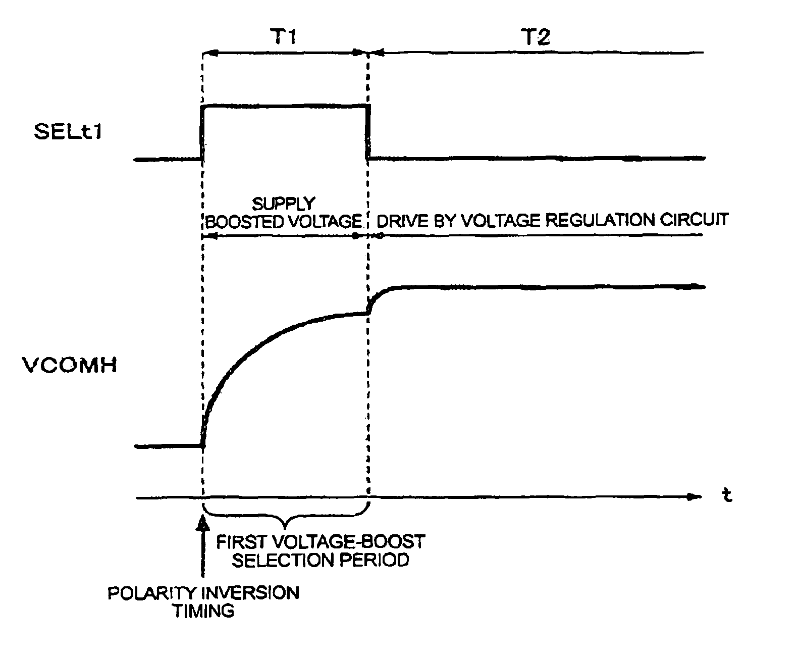
The invention provides a voltage supply circuit for an electro-optic device that can switch between different voltages and maintain the voltage of the electrodes at the second voltage after a boosted voltage has been supplied. This circuit includes a first voltage boost circuit and a charge supply circuit for supplying a charge to the electrodes. The invention also provides a power supply circuit for supplying a voltage to the opposing electrode in synchronization with polarity inversion timing. The invention also includes a display driver for driving the electro-optic device and an electro-optic device comprising a plurality of scanning lines, data lines, a pixel electrode, an opposing electrode, and the voltage supply circuit. The technical effects of the invention include improved voltage control and synchronization with polarity inversion timing for a more efficient display driver.

Problems solved by technology

Furthermore, supplying a voltage boosted by this charge-pump operation directly to the opposing electrode degrades picture quality because of a voltage decline caused by a leak between the opposing and pixel electrodes.
To avoid this degradation, a large-capacity capacitance element and a low-leak liquid crystal panel are required, which will in turn increase costs.
As a result, a large amount of power is consumed.

Method used


Image

  • Voltage supply circuit, power supply circuit, display driver, electro-optic device, and electronic apparatus
  • Voltage supply circuit, power supply circuit, display driver, electro-optic device, and electronic apparatus
  • Voltage supply circuit, power supply circuit, display driver, electro-optic device, and electronic apparatus

Examples


Embodiment Construction

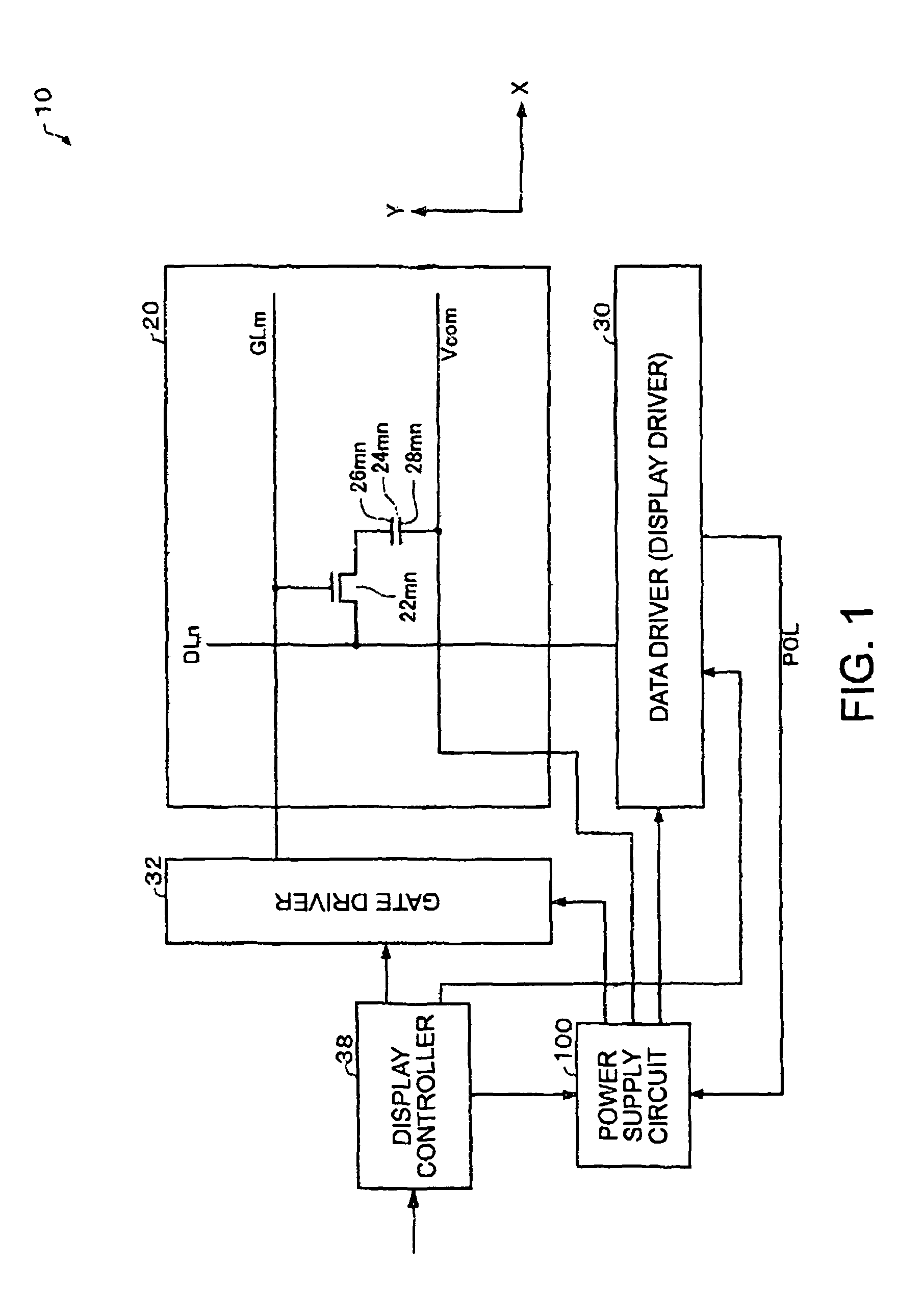
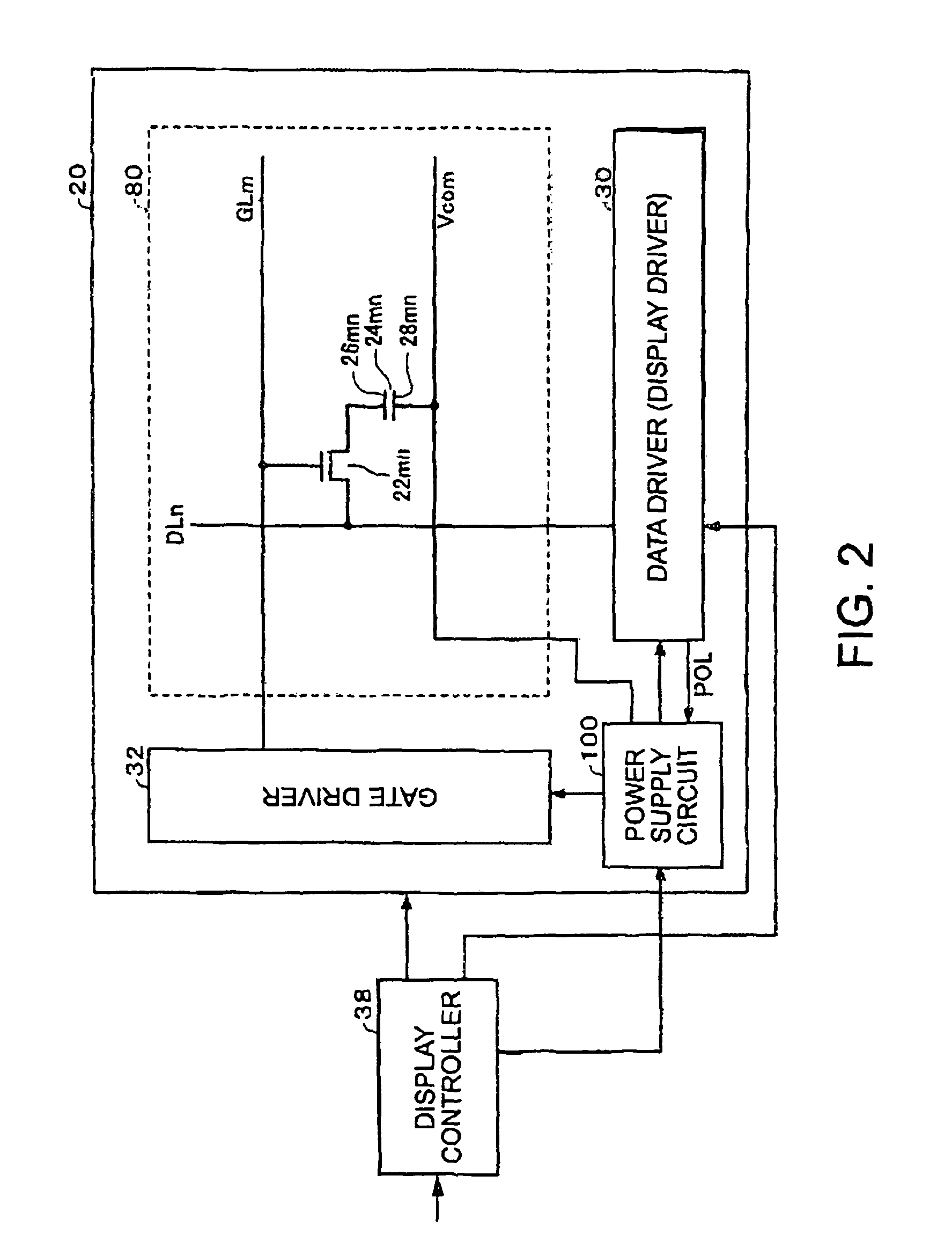
[0068]An advantage of the invention is to provide a power supply circuit, an opposing-electrode voltage supply circuit, a display driver, an electro-optic device and an electronic apparatus that can supply voltage to an electrode with high accuracy and low power consumption.

[0069]According to one embodiment of the invention, there is provided a voltage supply circuit which switches a first voltage supplied to an electrode to a second voltage, and supplies the second voltage to the electrode, the voltage supply circuit comprising: a first voltage boost circuit including a switching element for generating a boosted voltage boosted by charge-pump operation, and a charge supply circuit for supplying a charge to the electrode. When the first voltage is switched to the second voltage, the charge supply circuit supplies a charge to the electrode so as to maintain the voltage of the electrode at the second voltage after the boosted voltage has been supplied to the electrode.

[0070]Accordingl...


PUM


Abstract

A voltage supply circuit which switches a first voltage supplied to an electrode to a second voltage and supplies the second voltage to the electrode including: a first voltage boost circuit including a switching element for generating a boosted voltage boosted by charge-pump operation; and a charge supply circuit for supplying a charge to the electrode. When the first voltage is switched to the second voltage, the charge supply circuit supplies a charge to the electrode so as to maintain the voltage of the electrode at the second voltage after the boosted voltage has been supplied to the electrode.

Description

[0001]Japanese Patent Application No. 2004-279503, filed on Sep. 27, 2004, is hereby incorporated by reference in its entirety.BACKGROUND OF THE INVENTION[0002]The present invention relates to a voltage supply circuit, a power supply circuit, a display driver, an electro-optic device and an electronic apparatus.[0003]An active-matrix liquid crystal display includes a plurality of scanning lines and a plurality of data lines arranged in a matrix. The display also includes a plurality of switching elements each of which is coupled to a scanning line and a data line, and a plurality of pixel electrodes each of which is coupled to a switching element. Each pixel electrode is placed face to face with an opposing electrode with a liquid crystal (electro-optic material in a broad sense) therebetween.[0004]With the liquid crystal display of this configuration, voltage supplied to a data line via a switching element that has been turned on by a selected scanning line is applied to a pixel el...

Claims


Application Information

Patent Timeline
Patent Type & Authority Patents(United States)
IPC IPC(8): G06F3/038
CPCG09G3/3655G09G3/3614G09G2320/02G09G2330/02G09G2330/021
Inventor MORITA, AKIRA
Owner SEIKO EPSON CORP
Learn More