
Magnetic element temperature sensors

a technology of temperature sensors and magnetic elements, applied in the direction of instruments, electric/magnetic/electromagnetic heating, heat measurement, etc., can solve the problem of not completely eliminating the detectable re-magnetization pulse, etc., and achieve the effect of reliable temperature sensing and readily monitored

Active Publication Date: 2010-09-14
TSI TECH
View PDF63 Cites 31 Cited by
  • Summary
  • Abstract
  • Description
  • Claims
  • Application Information

AI Technical Summary

Benefits of technology

"The present invention provides a new type of temperature sensor that uses magnetically susceptible elements to monitor temperature. These elements have a characteristic re-magnetization response that is sensitive to changes in temperature, allowing for accurate temperature sensing. The sensor elements can be placed in thermal contact with an object and an alternating magnetic field is applied to cause the re-magnetization response. The sensor elements have different set point temperatures, which can be used to determine the temperature of the object. The invention also provides a detector for generating the alternating magnetic field and detecting the re-magnetization responses of the sensor elements. The sensor elements can be in the form of metallic bodies or microwires. The invention also provides a method of sensing the temperature of an object by placing the temperature sensor in thermal contact with the object and detecting the re-magnetization response of the sensor elements."

Problems solved by technology

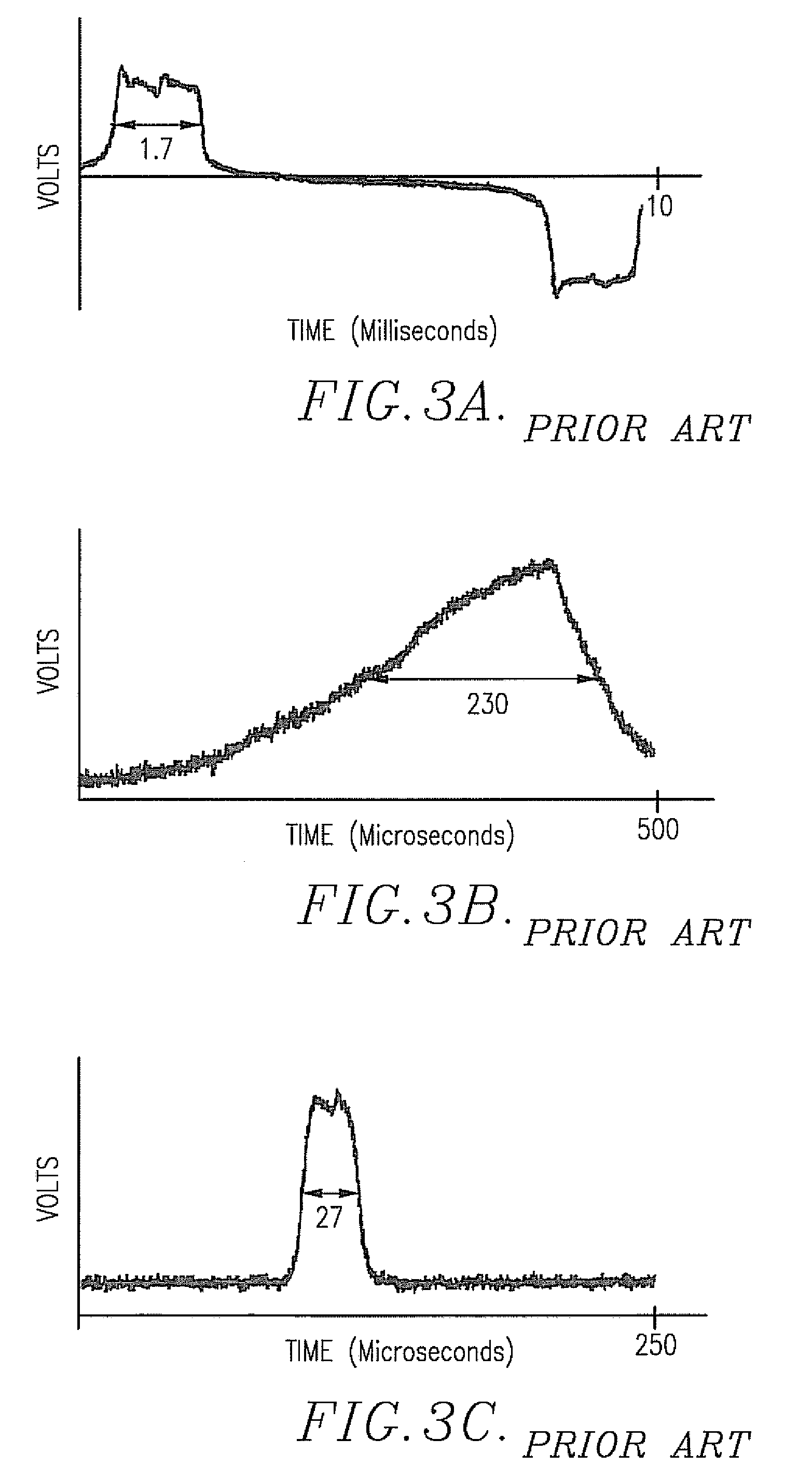
Additionally, changes in magnetic properties at temperatures close to the Curie temperatures of the individual temperature-sensing microwires can alter but not entirely eliminate the detectable re-magnetization pulses thereof.

Method used


Image

  • Magnetic element temperature sensors
  • Magnetic element temperature sensors
  • Magnetic element temperature sensors

Examples


first embodiment

ry Microwires for Curie Temperature Sensing

[0050]The first embodiment of the invention comprises a magnetic microwire temperature sensor having at least one and usually a plurality of magnetically susceptible microwires, with the individual alloys of at least certain of the microwires having modified chemistries and consequent different Curie temperatures, usually below about 400° C. Additionally, this embodiment includes a microwire reader or detector capable of decoding temperature information derived from the sensor microwires.

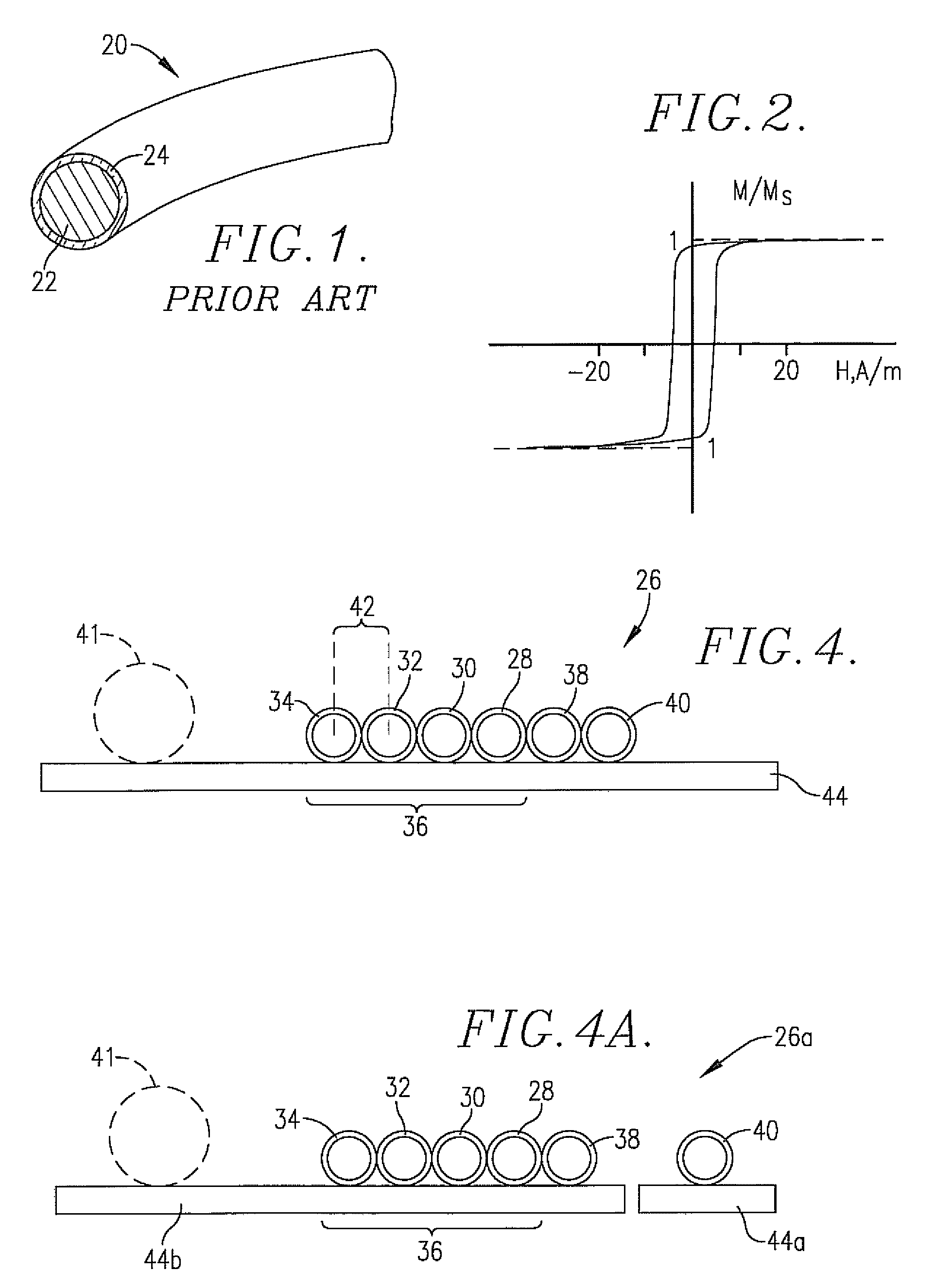
[0051]Chemically modified individual microwires are preferably fabricated so that the modified microwires retain large Barkhausen discontinuities, extremely low coercivities, and extremely high permeabilities below their respective Curie temperatures (with resultant hysteresis behavior of the type depicted in FIG. 2). These modified microwires essentially completely lose their ferromagnetism above their Curie temperatures. Other microwires within the array ...

second embodiment

erromagnetic Sheaths for Temperature Sensing

[0069]This second embodiment comprises a magnetic element temperature sensor 64 having a plurality of composite temperature-sensing microwires 66 each including a magnetically susceptible microwire of the prior art type described above that has no intentional reduction of its Curie temperature, such that it will retain its large Barkhausen discontinuity and other magnetic properties as depicted in FIG. 2 throughout the entire operating range of the sensor 64. This microwire structure further includes a surrounding, tubular, structure 68. The overall second embodiment further includes a microwire temperature detector similar to detector 46 having stored algorithm(s) capable of decoding the temperature information derived from interrogation of the sensor 64.

[0070]In particular, each of the composite microwires 66 has an innermost alloy 70 surrounded by an intermediate glass coating 72, such that this inner portions of the composite microwire...

third embodiment

Seperate but Adjacent Ferromagnetic Saturation Elements for Temperature Sensing

[0087]The third embodiment is conceptually very similar to the second embodiment and differs in the use of ferromagnetic sheath saturation or biasing elements as separate entities which do not need to touch the surface of the adjacent temperature-sensing microwires, as compared with the sheaths 74 of the second embodiment which are bonded or otherwise affixed to central microwire structure. Referring to FIG. 7, a combination microwire 92 is illustrated and includes a microwire 20 of the type previously described that has no intentional reduction of its Curie temperature, such that it will retain its large Barkhausen discontinuity and other magnetic properties as depicted in FIG. 2 throughout the entire operating range of the sensor. Also, the combination microwire 92 includes an adjacent ferromagnetic sheath 94. The sheath 94 is located near enough to the associated microwire 20 so as to prevent by magnet...


PUM

PropertyMeasurementUnit
temperatureaaaaaaaaaa
temperaturesaaaaaaaaaa
temperatureaaaaaaaaaa

Abstract

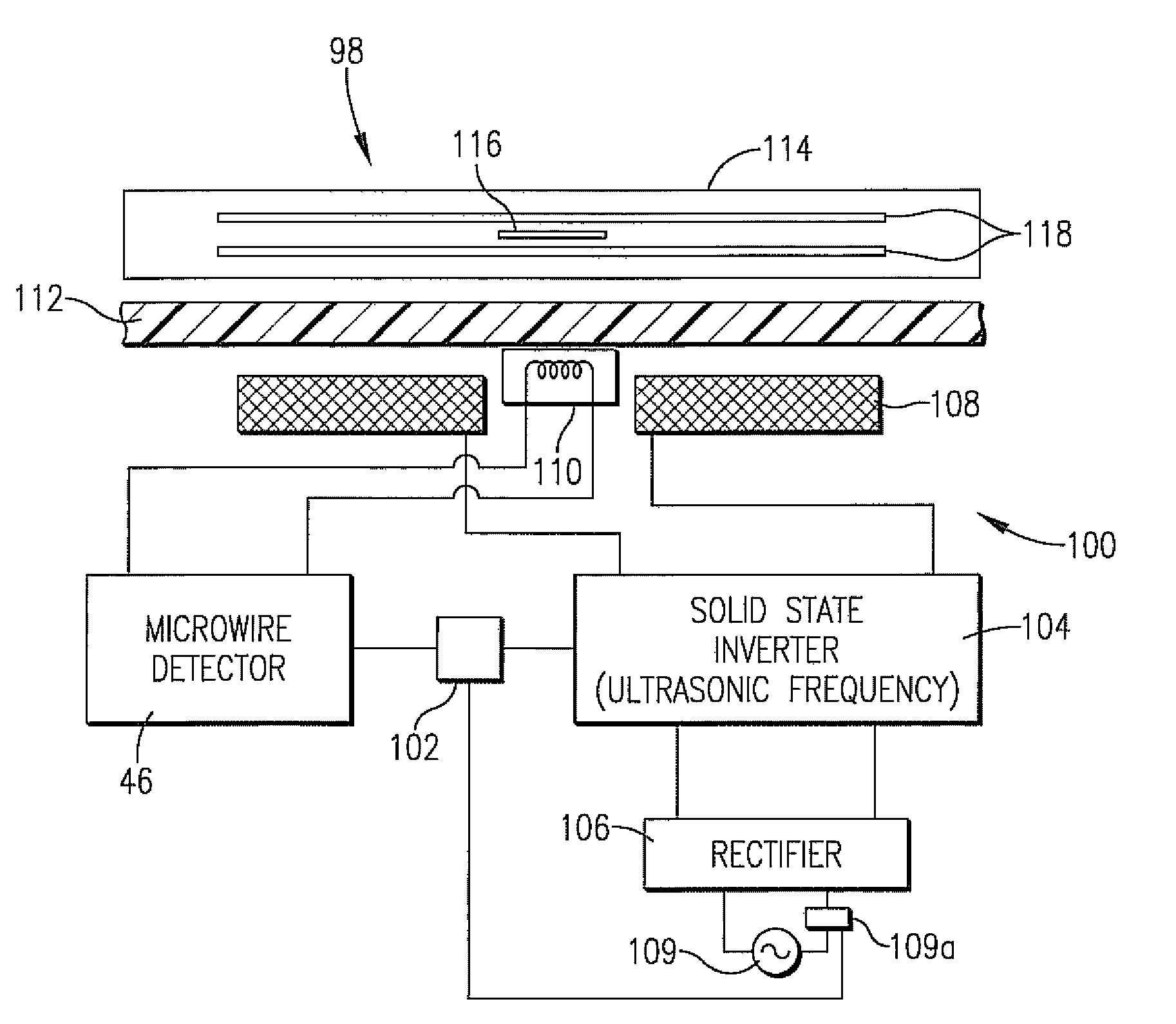
Small, low-cost wireless temperature sensors (26,64,96) are provided for sensing the temperature of an object (44). The temperature sensors (26,64,96) preferably include a plurality of individual, magnetically susceptible temperature sensor elements (28-34,66,92), as well as optional magnetic field-responsive data elements (38,40,20) adapted for attachment to object (44) or to a substrate (82) in turn attached to object (44). The temperature sensor elements (28-34,66,92) preferably have magnetic bodies (22,70) exhibiting a re-magnetization response under the influence of an applied alternating magnetic field, which is different below and above a set point temperature, normally the Curie temperature of the magnetic body (22) or an adjacent sheath (74,94). The temperature sensors (26,64,96) are used in conjunction with a detector (46) operable to generate a magnetic field of magnitude sufficient to cause re-magnetization responses of the temperature sensor elements (28-34,66,92) and optional data elements (38,40,20), to detect such responses, and to use the detected responses to determine the temperature of object (44) by means of a decoding algorithm. The temperature sensors (26,64,96) can be used in closed-loop heating systems (98) capable of controlling the heating of an object (114).

Description

CROSS REFERENCE TO RELATED APPLICATIONS[0001]This application claims the benefit of Application Ser. No. 60 / 836,448, filed Aug. 9, 2006, Application Ser. No. 60 / 818,385, filed Jul. 5, 2006, and Application Ser. No. 60 / 798,591 filed May 9, 2006. Each of the foregoing applications is incorporated by reference herein.BACKGROUND OF THE INVENTION[0002]1. Field of the Invention[0003]The present invention is broadly concerned with magnetic element temperature sensors, detectors for use with such sensors, closed-loop heating systems making use of the sensors and detectors to wirelessly determine the temperature of an object and to control the object's temperature, and corresponding methods. More particularly, the invention is concerned with temperature sensors made up of at least one magnetically susceptible sensor element, preferably formed of amorphous or nanocrystalline metal, and having a re-magnetization response under the influence of an applied alternating magnetic field which is dif...

Claims


Application Information

Patent Timeline
Patent Type & Authority Patents(United States)
IPC IPC(8): G01K7/00
CPCG01K7/36H05B6/062H05B2213/06
Inventor CLOTHIER, BRIAN L.ABBETT, EDWIN T.
Owner TSI TECH
Learn More