
Process and catalyst for hydrogenation of carbon oxides

a carbon monoxide and catalyst technology, applied in the direction of physical/chemical process catalysts, metal/metal-oxide/metal-hydroxide catalysts, hydrocarbon preparation catalysts, etc., can solve the problems of reducing the effectiveness of co, undesired carbon monoxide in feed gases, and high undesirable co presence, so as to improve the methane activity of carbon monoxide and dioxide to methane

Inactive Publication Date: 2010-09-07
HALDOR TOPSOE AS
View PDF4 Cites 30 Cited by
  • Summary
  • Abstract
  • Description
  • Claims
  • Application Information

AI Technical Summary

Benefits of technology

The present invention provides a new catalyst for the hydrogenation of carbon oxides that improves the activity and selectivity of the process. The catalyst is made of bimetallic iron-nickel or iron-cobalt alloy supported on an oxide carrier. The iron-nickel atomic ratio is between 0.1 and 0.8, preferably between 0.2 and 0.5. The catalyst has a high CO hydrogenation activity and high conversion rates of carbon oxides. The activity is influenced by the pressure employed in the reaction, with high conversion rates of carbon oxides being achieved at a pressure of above 20 bar. The invention also provides a process for hydrogenation of carbon oxides using this new catalyst.

Problems solved by technology

The presence of carbon monoxide in feed gases is undesired in a number of processes.
In a fuel cell, such as a Polymer Electrolyte Membrane Fuel Cell, the presence of carbon monoxide is very critical since it can poison the noble metal electrodes used in fuel cells and therefore reduce their effectiveness.
Similarly, in ammonia production plants, the presence of CO is also highly undesirable in the ammonia synthesis reactor and the carbon oxide concentrations should usually be reduced to values as low as 5-10 ppmv.
This requirement places certain limitations on practical methods for manufacturing such catalysts.

Method used


Image

  • Process and catalyst for hydrogenation of carbon oxides
  • Process and catalyst for hydrogenation of carbon oxides
  • Process and catalyst for hydrogenation of carbon oxides

Examples


example 1

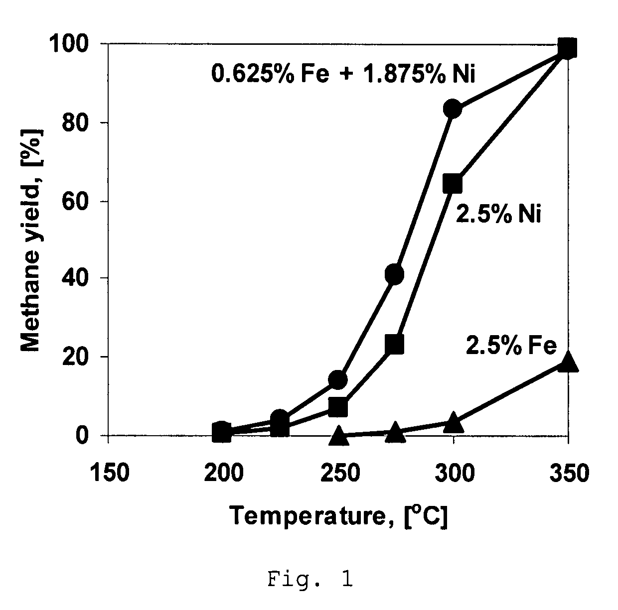
[0040]A comparative Ni-containing catalyst was prepared using incipient wetness impregnation of spinel-type MgAl2O4 support having particle size from 0.25 mm to 0.5 mm and having pore volume of about 0.7 cm3 / g and a surface area of about 70 m2 / g with an aqueous solution of nickel nitrate (Ni(NO3)2) such that the resulting catalyst has about 2.5 wt % Ni. Prior to the impregnation the support was dried in the oven at 200° C. for 5 hours. A period of about 4 hours was allowed for the salt solution to fill the pores of the carrier. The impregnated spinel is then dried at room temperature for 12 hours and then heated in air up to 500° C. with a heating rate of 2.5° C. per minute and kept at 500° C. for 5 hours.

example 2

[0041]A comparative catalyst is prepared following the method of Example 1 except that nickel nitrate is replaced by the iron nitrate, Fe(NO3)3, to obtain a catalyst containing about 2.5 wt % Fe.

example 3

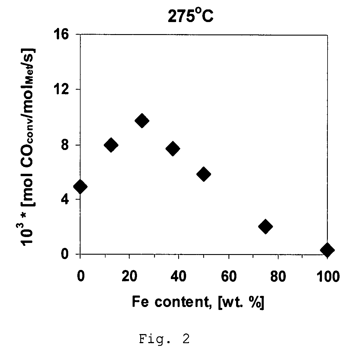
[0042]A catalyst is prepared using incipient wetness impregnation of support as in Example 1 except that the concentration of Ni(NO3)2 is decreased to obtain 2.1875 wt % Ni in the resulting catalyst. After impregnation the sample was dried at room temperature for 12 hours and impregnated with the solution of Fe(NO3)3 to obtain an iron concentration in the resulting catalyst of about 0.3125 wt %. Impregnated catalyst is then dried at room temperature for 12 hours and then heated in air up to 500° C. with a heating rate of 2° C. per minute and kept at 500° C. for 5 hours.


PUM

PropertyMeasurementUnit
total pressureaaaaaaaaaa
reaction temperatureaaaaaaaaaa

Abstract

A process for hydrogenation of carbon oxides comprising contacting a gas mixture containing carbon oxides and of hydrogen with a catalyst comprising bimetallic iron-nickel or iron-cobalt alloys as the active catalytic material supported on a carrier of an oxide. The carrier is preferably formed to have a surface area greater than 20 m2 / g.

Description

BACKGROUND OF THE INVENTION[0001]The present invention concerns a process and a catalyst for the hydrogenation of the carbon oxides carbon monoxide and carbon dioxide. More specifically, this invention relates to a process for reacting or removing carbon oxides by hydrogenation using a catalyst comprising a support and an active component being of the composition of alloys of Ni, Fe and Co metals in oxide or reduced form.[0002]The presence of carbon monoxide in feed gases is undesired in a number of processes.[0003]In a fuel cell, such as a Polymer Electrolyte Membrane Fuel Cell, the presence of carbon monoxide is very critical since it can poison the noble metal electrodes used in fuel cells and therefore reduce their effectiveness.[0004]Preferably, the CO concentration for fuel cell feed should be less than 100 ppm, more preferably less then 50 ppm. However, the initial concentration of CO, as received from the fuel processor, can exceed 1 wt %. Therefore, further reduction of CO ...

Claims


Application Information

Patent Timeline
Patent Type & Authority Patents(United States)
IPC IPC(8): C07C27/00
CPCB01J23/75B01J23/755C07C1/044C07C9/04B01J21/005B01J23/745B01J23/78B01J37/0201C07C2523/75C07C2523/755H01M8/0668Y02E60/50
Inventor CHRISTENSEN, CLAUS HVIIDANDERSSON, MARTINKUSTOV, ARKADYJOHANNESEN, TUEBLIGAARD, THOMASLARSEN, KASPER E.NORSKOV, JENS K.SEHESTED, JENS
Owner HALDOR TOPSOE AS
Learn More