
Economical methods and injection apparatus for high pressure die casting process

Inactive Publication Date: 2010-08-31
DAI ZHONGNAN
View PDF13 Cites 11 Cited by
  • Summary
  • Abstract
  • Description
  • Claims
  • Application Information

AI Technical Summary

Benefits of technology

[0017]2) To eliminate molten metal pouring time by loading metal into the sleeve before the mold closes.
[0018]3) To eliminate electronic/hydraulic control circles for low impact and transition of slow injection and fast injection.
[0019]Disclosed are economical methods and apparatuses for high-pressure die-casting. The method of the invention uses three plungers (pistons), of which one is mounted on a fixed back plate. This unit reduces metal loading time, entrapped gases during fast injection, impact force on a movable mold from fast injection.
[0020]Other met

Problems solved by technology

With conventional control systems, however, as the velocity of the flow of the molten metal into the cavity increases, the impact pressure that the metal exerts on the die increases.
At some point, that pressure might be sufficiently high to overcome the clamping force, causing the die halves to separate and allow metal to leak from the cavity, thereby destroying the integrity of the cast part.
However, the internal gas pressure of the cavity has a limited vacuum ran

Method used


Image

  • Economical methods and injection apparatus for high pressure die casting process
  • Economical methods and injection apparatus for high pressure die casting process
  • Economical methods and injection apparatus for high pressure die casting process

Examples


Example

REFERENCE NUMERALS IN DRAWINGS

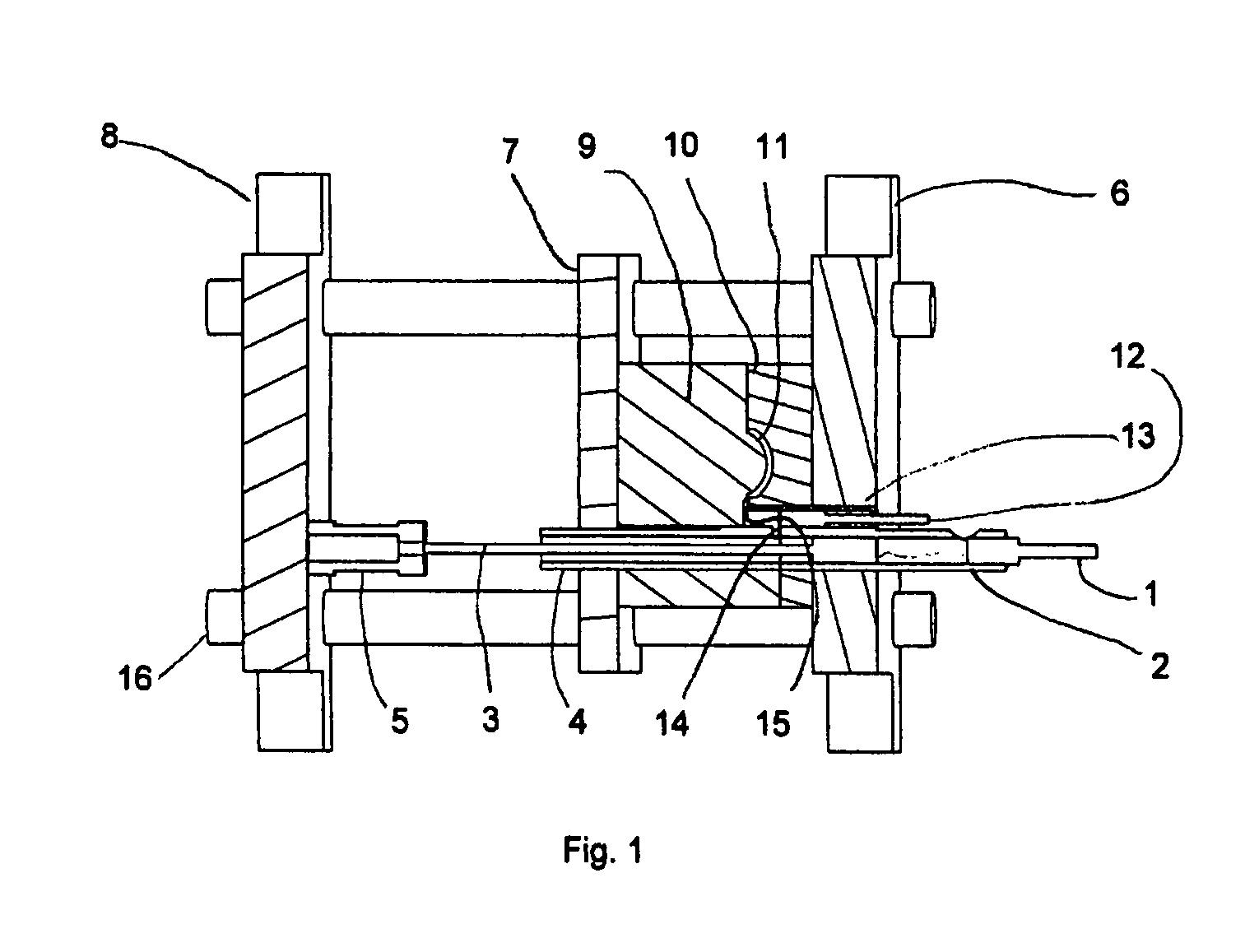
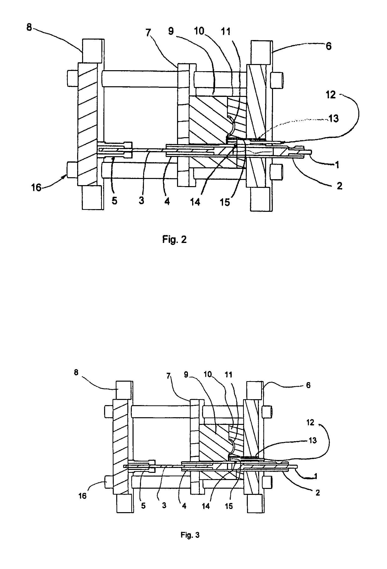
[0029]1 injection plunger, 2 injection sleeve, 3 assistant plunger, 4 assistant sleeve 5 hydraulic cylinder, 6 stationary plate, 7 movable plate, 8 back plate, 9 movable mold 10 stationary mold, 11 cavity, 12 intensification plunger, 13 intensification sleeve 14 runner, 15 gate, 16 tie bar

[0030]As shown in FIG. 1:

[0031]The die casting apparatus includes a stationary plate 6, a stationary mold 10, a movable plate 7, and a movable mold 9. Stationary mold 10 is fixed to Stationary plate 6. Movable mold 9 is fixed to movable plate 7, which is advances to and retracts from stationary mold 10 to open and close the entire mold. When the entire mold is closed, a cavity 11 is formed between stationary mold 10 and movable mold 9.

[0032]Stationary plate 6 and stationary mold 10 are provided with two plunger-sleeve-receiving holes into which injection sleeve 2 and an intensification sleeve 13 are fitted. The inner space of injection sleeve 2 is connected to the inne...


PUM

PropertyMeasurementUnit
Pressureaaaaaaaaaa
Speedaaaaaaaaaa

Abstract

A method of and an apparatus for high pressure die casting are disclosed. The method uses a die casting apparatus which comprises a group of three plungers for casting metal. The two of which, injection plunger 1 and assistant plunger 3, are used to reduce metal loading time and reduce entrapped gases in die casting during a fast injection stage. By moving into injection sleeve 2, the assistant plunger separates the mold cavity 11 from the space defined by assistant plunger 3, injection sleeve 2, and injection plunger 1. The flow power device for moving said assistant plunger 3 is mounded on a back plate 8. A third plunger, the intensification plunger 12, is used to squeeze casting as soon as the injection plunger advances to a position in which the runner is separated from the closed space. This separated injection and intensification systems eliminates slow shot speed and fast shot deceleration stages and can use a position-limiting switch to start intensification which eliminates the need for a complex hydraulic valve system.

Description

CROSS-REFERENCE TO RELATED APPLICATIONS[0001]This application claims the benefit of provisional patent application Ser. No. 60 / 930,859, filed on May 19, 2007.FEDERALLY SPONSORED RESEARCH[0002]Not ApplicableSEQUENCE LISTING OR PROGRAM[0003]Not ApplicationBACKGROUND[0004]1. Field of Invention[0005]This invention relates to economical methods and apparatuses for manufacturing a high-pressure die casting.[0006]2. Prior Art[0007]In a conventional die-casting method, a mold or die typically includes at least two mating parts that can be separated to facilitate removal of the cast part when it has cooled sufficiently. Only when the mold is closed could the molten metal be poured into the sleeve of a die casting machine. The molten metal is then forcibly injected into the mold cavity. For the purpose of simplicity, the mold or die will be described herein with reference to two mating parts or halves. Until the metal is cool enough to be removed, the mold halves must be held together under p...

Claims


Application Information

Patent Timeline
IPC IPC(8): B22D17/08B22D18/02B22D27/11
CPCB22D17/08B22D18/02B22D27/11
Inventor DAI, ZHONGNAN
Owner DAI ZHONGNAN
Learn More