
Cyclone core machining method

A processing method and swirl core technology, applied in the field of swirl core processing, can solve the problems of complex dimensional accuracy requirements of swirl core structure, long processing cycle and turnaround time, poor part size consistency, etc., so as to reduce the operation intensity of performance debugging , improve dimensional consistency and surface quality, and ensure the effect of machining accuracy

Inactive Publication Date: 2020-09-25
AECC AVIATION POWER CO LTD
View PDF5 Cites 2 Cited by
  • Summary
  • Abstract
  • Description
  • Claims
  • Application Information

AI Technical Summary

Problems solved by technology

[0004] Due to the complex structure of the swirl core and high dimensional accuracy requirements, the existing processing method is mainly based on the size of the swirl core, select the swirl core wool with a size similar to that of the finished product, and punch the center hole on the outer circle of the swirl core wool, directly Determine the length of the swirl core; then proceed to the structural processing of other parts of the swirl core; since the length and dimension finishing has been completed, other parts may be easily clamped and scrapped during the machining and switching clamping process of other parts; and the processing The cycle and turnaround time is long, the cutting processing time is 2 hours / piece, the processing cycle is about 50 days / 100 pieces, and the average pass rate is 69%; the efficiency of turning multi-thread grooves is low, the luminosity is poor, and the size of the parts is unstable; During grinding, it is difficult to ensure the R0.3max at the corner of the outer cylindrical surface and the left end surface, which leads to poor dimensional consistency of the parts and makes it difficult to debug the component flow rate. The current debugging pass rate is only 60%.

Method used


Image

  • Cyclone core machining method
  • Cyclone core machining method
  • Cyclone core machining method

Examples


Embodiment

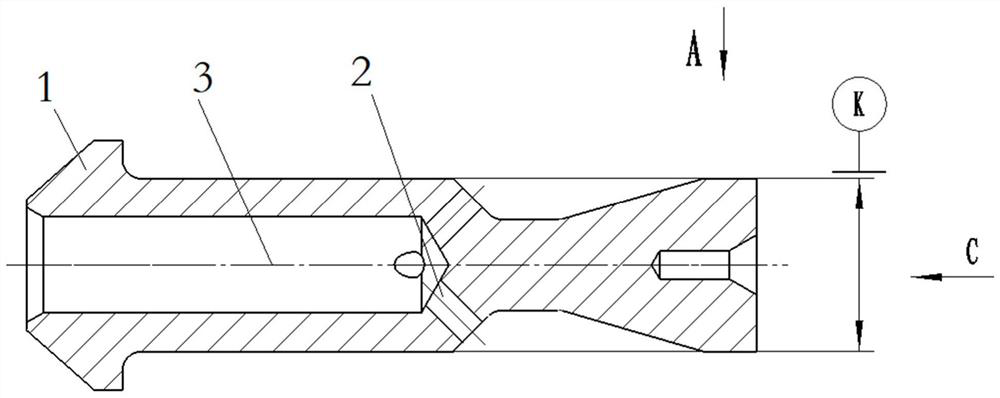
[0048] (1) Take the wool of the swirl core whose length is longer than the length of the swirl core to be formed after the turning and milling clamp, and install the wool of the swirl core on the turning and milling spindle. The size of the swirl core to be formed is as follows Figure 5 As shown; this application installs a Φ10 circlip on the main shaft, and a Φ5 circlip on the sub-spindle;

[0049] (2) Turning and milling swirl core wool inner shape and drilling, see the process diagram Figure 6 :

[0050] Step 1: The main shaft clamps the wool, the flat end face, rough and fine car shape, get as follows Figure 6a Swirl core wool structure, the processing process is summarized to ensure the relevant dimensions; the tool used: 85° outer circle turning tool;

[0051] Step 2: Drill the center hole to get such as Figure 6 b swirl core wool structure, the processing process is summarized to ensure the relevant dimensions; the tool used: ф0.8 center drill;

[0052] Step 3: ...


PUM


Abstract

The invention discloses a cyclone core machining method. According to the cyclone core machining method, a cyclone core blank longer than a cyclone core to be formed is selected; through one-time clamping of a spindle, machining of one end face and the outer surface of the cyclone core is completed without repeated clamping, the disassembling and assembling frequency is reduced, machining is carried out based on primary benchmark, and the machining precision is improved; meanwhile, the clamping frequency is reduced, the machining efficiency is improved, and the cycle is shortened; through coaxial clamping of an auxiliary shaft of a lathe, forming machining of the other end face of the cyclone core is completed, the machining coaxiality is ensured, and the machining precision can be effectively guaranteed; and finally, the surface of the cyclone core is subjected to surface grinding treatment, the size consistency and surface quality of cyclone core parts are improved, the performance debugging operation intensity of assembling the cyclone core to an assembly is reduced, and the debugging pass rate and efficiency are improved.

Description

technical field [0001] The invention belongs to the field of processing swirl core parts, and in particular relates to a swirl core processing method. Background technique [0002] The swirl core is an important part of the nozzle. The quality of its processing directly affects the performance of the auxiliary oil circuit of the nozzle. It has the characteristics of complex structure, high dimensional accuracy and high technical requirements. The sealing surface generally adopts the "spherical surface", "cone surface" or "plane" method, the mating surface generally adopts the "cylindrical surface" clearance fit method, and the flow oil passage generally adopts the "cylindrical surface / Inner cavity slotted type" and "end surface / cone uniformly distributed straight hole type", swirl oil passage generally adopts "uniformly distributed rectangular straight groove type", "multi-head worm spiral groove type" or "uniformly distributed straight hole type" . [0003] In terms of p...

Claims


Application Information

Patent Timeline
Patent Type & Authority Applications(China)
IPC IPC(8): B23P15/00
CPCB23P15/00
Inventor 张立义韩新艳席丽娜刘点涂娇董少锋朱阳许斌
Owner AECC AVIATION POWER CO LTD
Learn More