Polarizer and flat panel display apparatus including the same

a flat panel display and polarizer technology, applied in the direction of instruments, discharge tubes, luminescent screens, etc., can solve the problems of limiting the enhancement of contrast, lowering contrast and visibility, and more serious problems, so as to achieve the effect of enhancing contrast and visibility

Active Publication Date: 2010-08-10
SAMSUNG DISPLAY CO LTD
View PDF15 Cites 7 Cited by
  • Summary
  • Abstract
  • Description
  • Claims
  • Application Information

AI Technical Summary

Benefits of technology

[0008]Exemplary embodiments according to the present invention provide a polarizer capable of enhancing the contrast and visibility of a flat panel display apparatus, and a flat panel display apparatus including the same.

Problems solved by technology

However, flat panel display apparatuses have problems in that contrast and visibility are lowered due to sunlight reflection when images are viewed outdoors.
In particular, this problem is more serious in organic light-emitting display apparatuses because such reflection severely occurs on a metal reflective layer.
Here, the grids formed of a metal material reflect external light due to the characteristics of the material, which limits an enhancement in contrast.

Method used


Image

  • Polarizer and flat panel display apparatus including the same
  • Polarizer and flat panel display apparatus including the same
  • Polarizer and flat panel display apparatus including the same

Examples


Embodiment Construction

[0063]The present invention will now be described more fully with reference to the accompanying drawings, in which exemplary embodiments of the invention are shown.

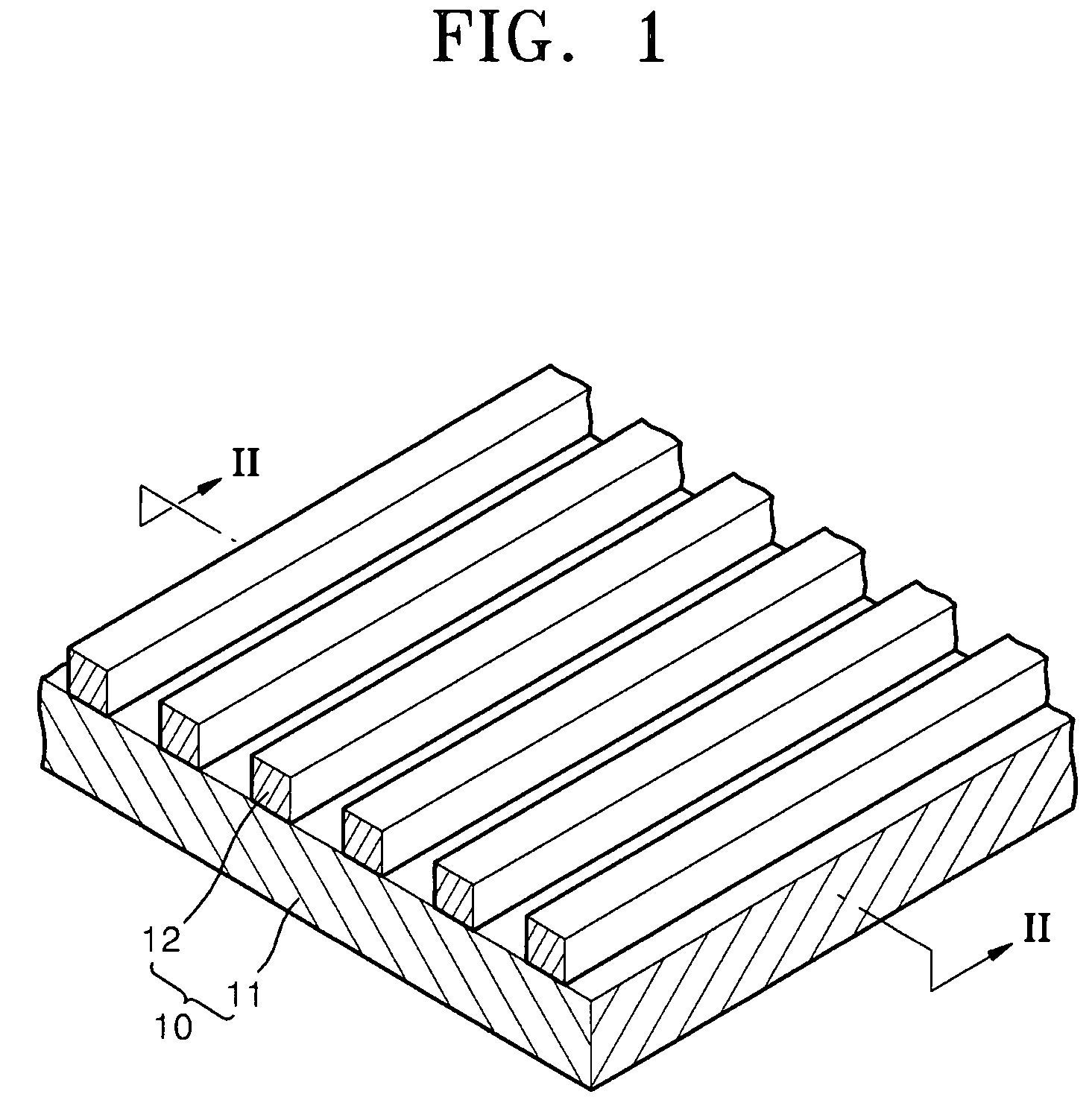
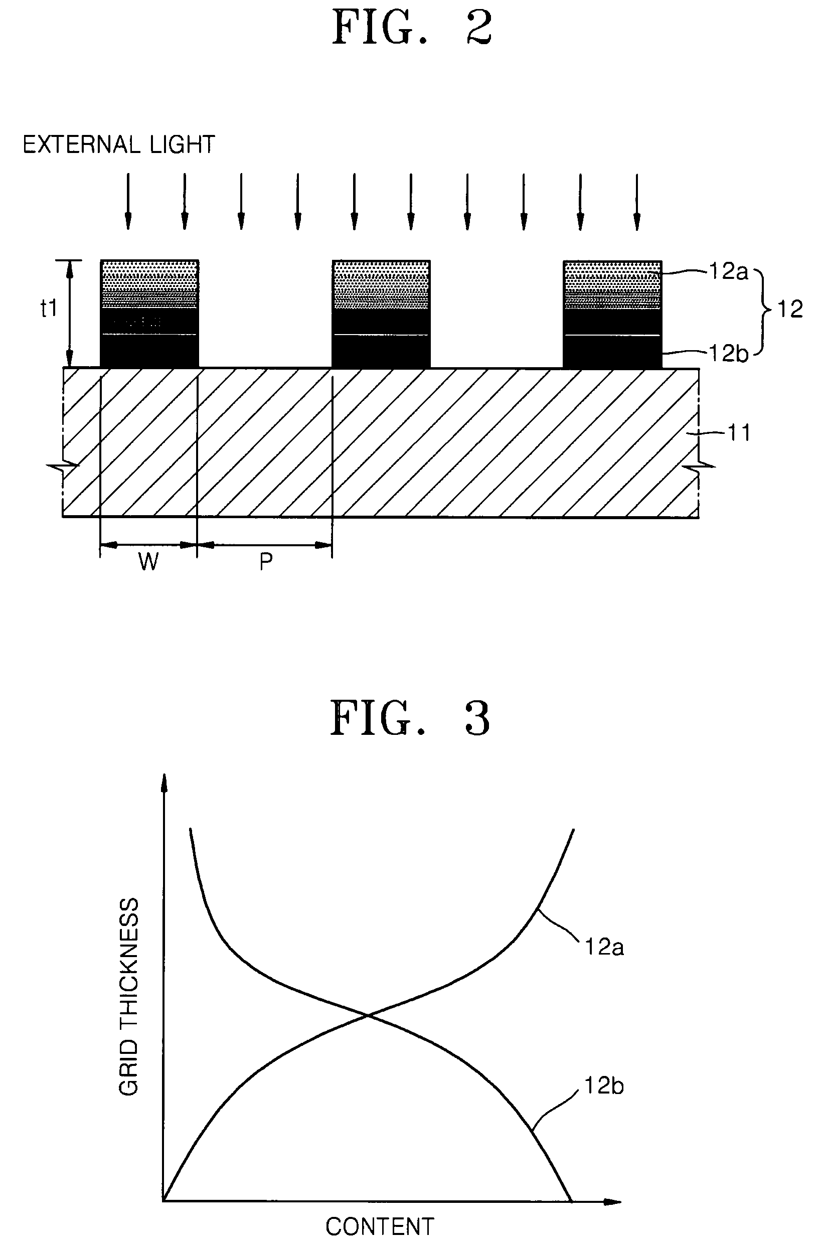
[0064]FIG. 1 is a schematic perspective view illustrating a polarizer according to an embodiment of the present invention, and FIG. 2 is a partial sectional view taken along a line II-II of FIG. 1. FIG. 3 is a graph illustrating the content (i.e., concentration) of a first component and a second component along the thickness direction of grids in the polarizer of FIG. 2.

[0065]Referring to FIGS. 1 and 2, a polarizer 10 includes a base 11 and a plurality of grids 12. The base 11 may be formed of a transparent material in order to allow light generated from a display apparatus in which the polarizer 10 is to be disposed to efficiently pass through the polarizer 10. For this, the base 11 may be formed of glass or a flexible plastic. In order for the base 11 to be formed as a film, in one embodiment, the base 11 is formed usin...


PUM

PropertyMeasurementUnit
thickness t1aaaaaaaaaa
widthaaaaaaaaaa
thickness t2aaaaaaaaaa

Abstract

A polarizer and a flat panel display apparatus including the polarizer are provided. The polarizer includes: a base; and a plurality of grids on the base, the plurality of grids including a first component and a second component, and having a thickness in a thickness direction of the polarizer. The first component includes a dielectric material and the second component includes a metal. The first component and the second component have a concentration gradient in the thickness direction, wherein a concentration of the first component in the grids increases along a thickness direction toward the external light incidence side, and a concentration of the second component in the grids increases along a thickness direction away from the external light incidence side.

Description

CROSS-REFERENCE TO RELATED PATENT APPLICATION[0001]This application claims priority to and the benefit of Korean Patent Application No. 10-2007-0021159, filed on Mar. 2, 2007, and Korean Patent Application No. 10-2007-0024191, filed on Mar. 12, 2007, in the Korean Intellectual Property Office, the disclosures of which are incorporated herein in their entirety by reference.BACKGROUND OF THE INVENTION[0002]1.Field of the Invention[0003]The present invention relates to a polarizer and a flat panel display apparatus including the same.[0004]2.Description of the Related Art[0005]In recent years, display apparatuses have tended to be replaced by portable thin flat panel display apparatuses. Among flat panel display apparatuses, organic or inorganic light-emitting display apparatuses, which are self-emitting display apparatuses, have advantages such as a wide viewing angle, a good contrast, and a rapid response speed, and thus, are in the spotlight as next generation display apparatuses. O...

Claims


Application Information

Patent Timeline
Patent Type & Authority Patents(United States)
IPC IPC(8): H01J1/62
CPCG02B5/3058H01L51/5281C23C14/048H10K59/8791H10K50/86
Inventor OH, JONG-SEOKLEE, JONG-HYUKSONG, YOUNG-WOOHWANG, KYU-HWANLEE, JOON-GUHA, JAE-HEUNGPARK, CHUL-WOO
Owner SAMSUNG DISPLAY CO LTD
Why Eureka
Try Eureka