
Connecting structure between electrode and lead, electric double layer capacitor having the same, and method for manufacturing the capacitor

a technology of double layer capacitors and connecting structures, which is applied in the direction of electrolytic capacitors, cell components, cell component details, etc., can solve the problems of relatively high contact resistance, inconvenient supersonic welding junctions, and insufficient junction force, so as to improve contact reliability of lead wires and minimize contact resistance

Active Publication Date: 2010-08-03
LS MATERIALS CO LTD
View PDF13 Cites 2 Cited by
  • Summary
  • Abstract
  • Description
  • Claims
  • Application Information

AI Technical Summary

Benefits of technology

The present invention provides a connecting structure between an electrode and a lead wire in an electric double layer capacitor that minimizes contact resistance between the electrode and the lead wire, improves contact reliability of the lead wire, and reduces the size of the capacitor. The invention also provides an electric double layer capacitor with the connecting structure and a method for manufacturing it. The technical effects of the invention include reducing the likelihood of failure of the connection between the electrode and lead wire, improving the reliability of the connection, and reducing the size of the capacitor.

Problems solved by technology

However, the supersonic welding junctions are not advantageous in that a sufficient junction force is not ensured due to the effects of a dielectric oxide layer formed on a surface of the positive electrode foil.
In addition, there is another problem that impurities caused by sparks generated during the supersonic welding process are adhered to the supersonic welding junctions.
However, there is a problem that a relatively high contact resistance is caused between the positive and negative electrode foils and the lead wires.
However, there is a problem that they give a lower junction force than the supersonic welding junctions and the caulking junctions.

Method used


Image

  • Connecting structure between electrode and lead, electric double layer capacitor having the same, and method for manufacturing the capacitor
  • Connecting structure between electrode and lead, electric double layer capacitor having the same, and method for manufacturing the capacitor
  • Connecting structure between electrode and lead, electric double layer capacitor having the same, and method for manufacturing the capacitor

Examples


experimental example 1

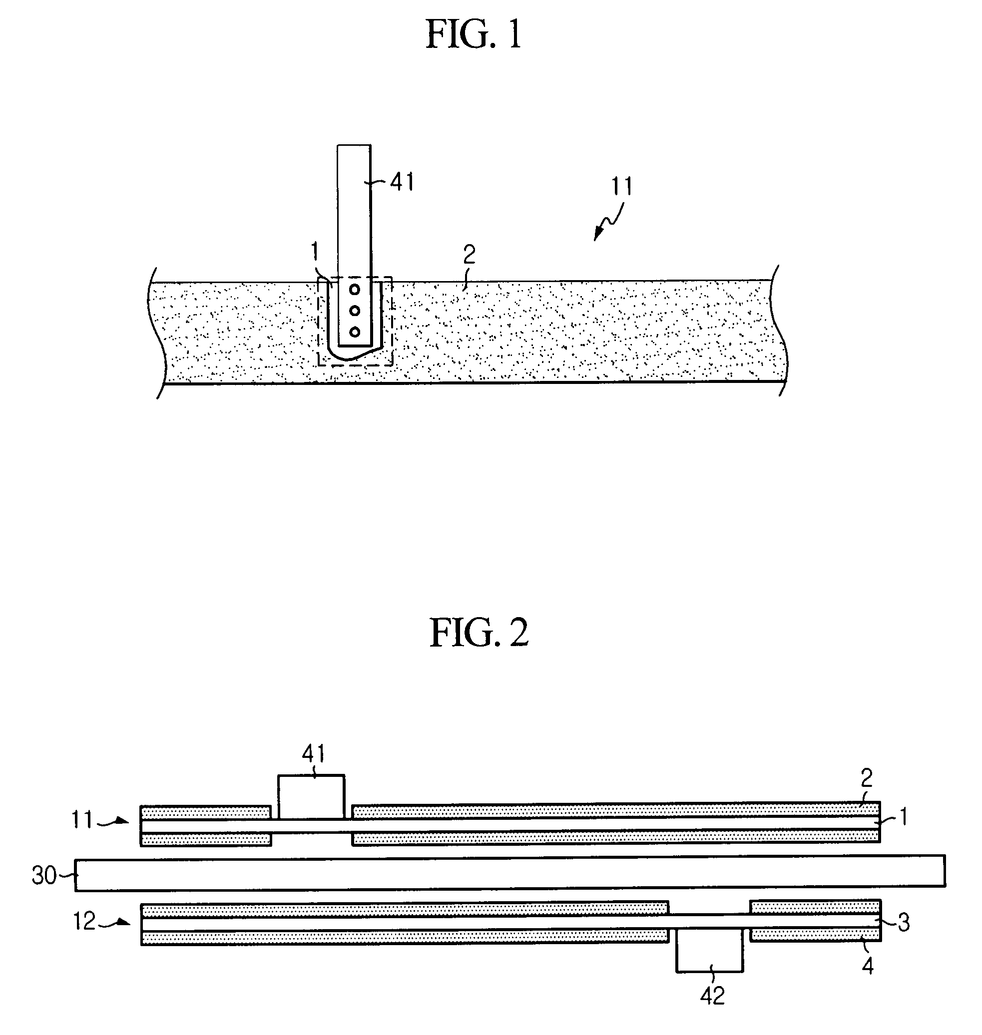
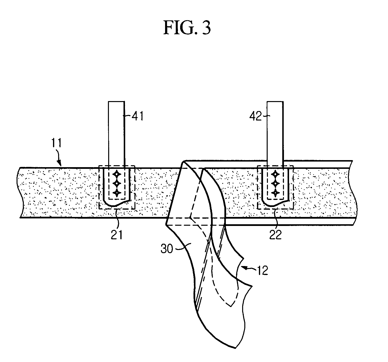
[0047]Five capacitors were configured according to the configuration shown in FIG. 3. When each capacitor was configured, an activated carbon coating was removed only from a region where a lead wire was to be joined to an electrode. In addition, a lead wire was joined to the electrode by using stitching and compressing at the same time. After that, the capacitors were taken up, and then average values of initial resistance values at 1 kHz, capacitances at a low current mode of 0.1A and capacitances at a high current mode of 3A were obtained.

experimental example 2

[0048]Five capacitors were configured like the Experimental Example 1. But, the activated carbon coating was removed not only from a region where a lead wire was to be joined to an electrode but also from a region opposite to the above region. In addition, a lead wire was joined to the electrode by using stitching and compressing at the same time. After that, the capacitors were taken up, and then average values of initial resistance values and capacitances of the capacitors were obtained under the same conditions as the Experimental Example 1.


PUM

PropertyMeasurementUnit
surface distanceaaaaaaaaaa
linear distanceaaaaaaaaaa
areaaaaaaaaaaa

Abstract

A connecting structure of a lead wire is electrically connected to an electrode in which a polarized electrode layer is formed on a surface of a current collector plate. A region of the electrode, to which the lead wire is to be joined, is free from the polarized electrode layer. The lead wire is joined to the current collector plate by means of stitching and then compressed thereto. This connecting structure may keep a capacitance of a capacitor and improve contact reliability. An electric double layer capacitor having the structure and a method for manufacturing the capacitor are also provided.

Description

BACKGROUND OF THE INVENTION[0001]1. Field of the Invention[0002]The present invention relates to a connecting structure between an electrode and a lead, an electric double layer capacitor having the structure, and a method for manufacturing the capacitor, and more particularly to a connecting structure between an electrode and a lead, which may keep a capacitance of a capacitor and improve contact reliability, an electric double layer capacitor having the structure, and a method for manufacturing the capacitor.[0003]2. Description of the Related Art[0004]An ultra capacitor has a capacitance at least 300 times of that of a conventional capacitor. In addition, the ultra capacitor may store a relatively smaller amount of energy than a battery, but it may supply an instantaneous peak power within a very short time about 10 to 100 times of a battery. Thus, the ultra capacitor is used as an energy device that substitutes or supplements a battery.[0005]An electric double layer capacitor, o...

Claims


Application Information

Patent Timeline
Patent Type & Authority Patents(United States)
IPC IPC(8): H01G9/00H01G9/008H01G11/00H01G11/22H01G11/42H01G11/66H01G11/74H01G11/84H01G11/86H01M2/26
CPCH01G9/016H01G9/155H01G11/84H01G11/74H01G11/42Y10T29/417Y02E60/13H02J50/20
Inventor KANG, JIN-ALEE, HEE-YOUNG
Owner LS MATERIALS CO LTD
Learn More