
Method of manufacturing optical element, and optical element

a manufacturing method and technology of optical elements, applied in the field of manufacturing optical elements and optical elements, can solve the problems of unendurable film formation on a base material such as a resin base material, adversely affecting the surface precision of optical substrates, and the inability to anticipate reflection reduction, etc., to achieve good reflection prevention characteristics

Inactive Publication Date: 2010-08-03
CANON KK
View PDF11 Cites 3 Cited by
  • Summary
  • Abstract
  • Description
  • Claims
  • Application Information

AI Technical Summary

Benefits of technology

[0015]As a result of exhaustive studies, the present inventors have found that after a film is formed on an optical substrate from a coating liquid containing a metal alkoxide containing at least aluminum and a stabilizer, the film is immersed in a water-containing liquid, and baked and then subjected to warm water treatment, whereby a film having an irregularity structure on its surface which has high reflection preventing performance can be obtained by baking at lower temperature than conventional baking.
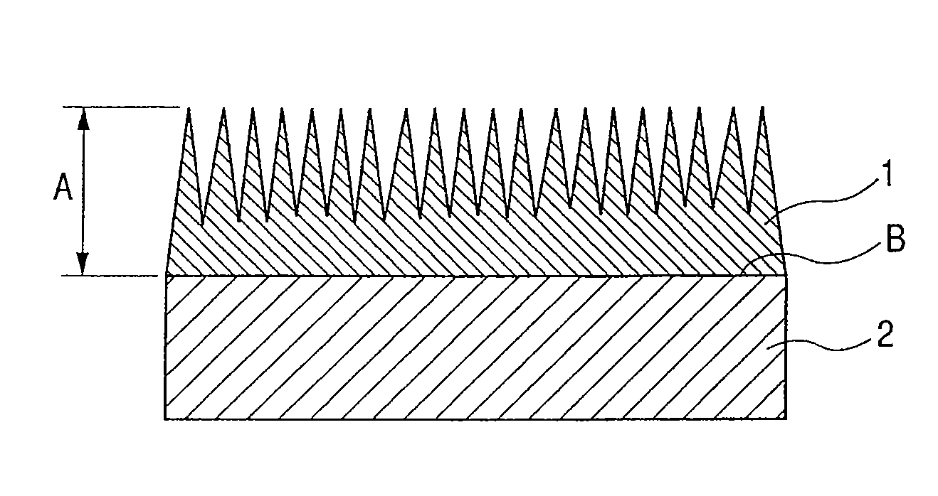
[0018]According to the present invention, a fine irregularity structure having a reflection preventing function can be formed at low temperature even by forming a film on an optical substrate surface from a coating liquid containing a metal alkoxide containing at least aluminum and a stabilizer, and an optical element having a good reflection preventing characteristic can be provided.

Problems solved by technology

In this case, the reflectance is a function of wavelength, and when the wavelength deviates from the designed central wavelength, the reflection reduction cannot be anticipated.
H09-202649, since baking temperature at the time of forming a film is commonly as high as not less than 400° C., the process poses problems such that the process adversely affects the surface precision of optical substrates, and a film cannot be formed on a base material such as a resin base material unendurable to a high temperature.
On the other hand, there is a case where after a film is formed by applying a coating liquid containing a metal alkoxide containing at least aluminum and a stabilizer on an optical substrate as in Japanese Patent Application Laid-Open No. 2001-017907, if the film is immersed in warm water without specially being baked, it is dissolved out and the surface irregularity texture cannot sufficiently be formed, thus excellent reflection preventing performance is not obtained in same cases.

Method used


Image

  • Method of manufacturing optical element, and optical element
  • Method of manufacturing optical element, and optical element
  • Method of manufacturing optical element, and optical element

Examples


example 1

[0074]A quartz substrate of 26 mm×76 mm in size and 1 mm in thickness was washed with a neutral detergent and then with pure water in order, and dried to prepare a glass substrate for coating.

[0075]23 parts by mass of aluminum sec-butoxide (Al(O-sec-Bu)3) was dissolved in 114 parts by mass of 2-propanol (IPA), and 12 parts by mass of ethyl acetoacetate (EAcAc) as a stabilizer was added to the solution, and stirred for about 3 hours at room temperature to prepare an Al2O3 sol solution as a coating liquid. The molar ratio of the solution was set at Al(O-sec-Bu)3:IPA:EAcAc=1:20:1.

[0076]Then, the glass substrate for coating (refractive index ne=1.524) was immersed in the coating liquid, and thereafter, a coating film was formed on the glass substrate surface by a dipping method (pull-up speed of 2 mm / sec, 20° C., 56% R.H.).

[0077]The coated glass substrate was preliminarily dried at 300° C. for 10 minutes, then immersed in distilled water of 30° C. for 10 minutes to remove the stabilizer...

example 2

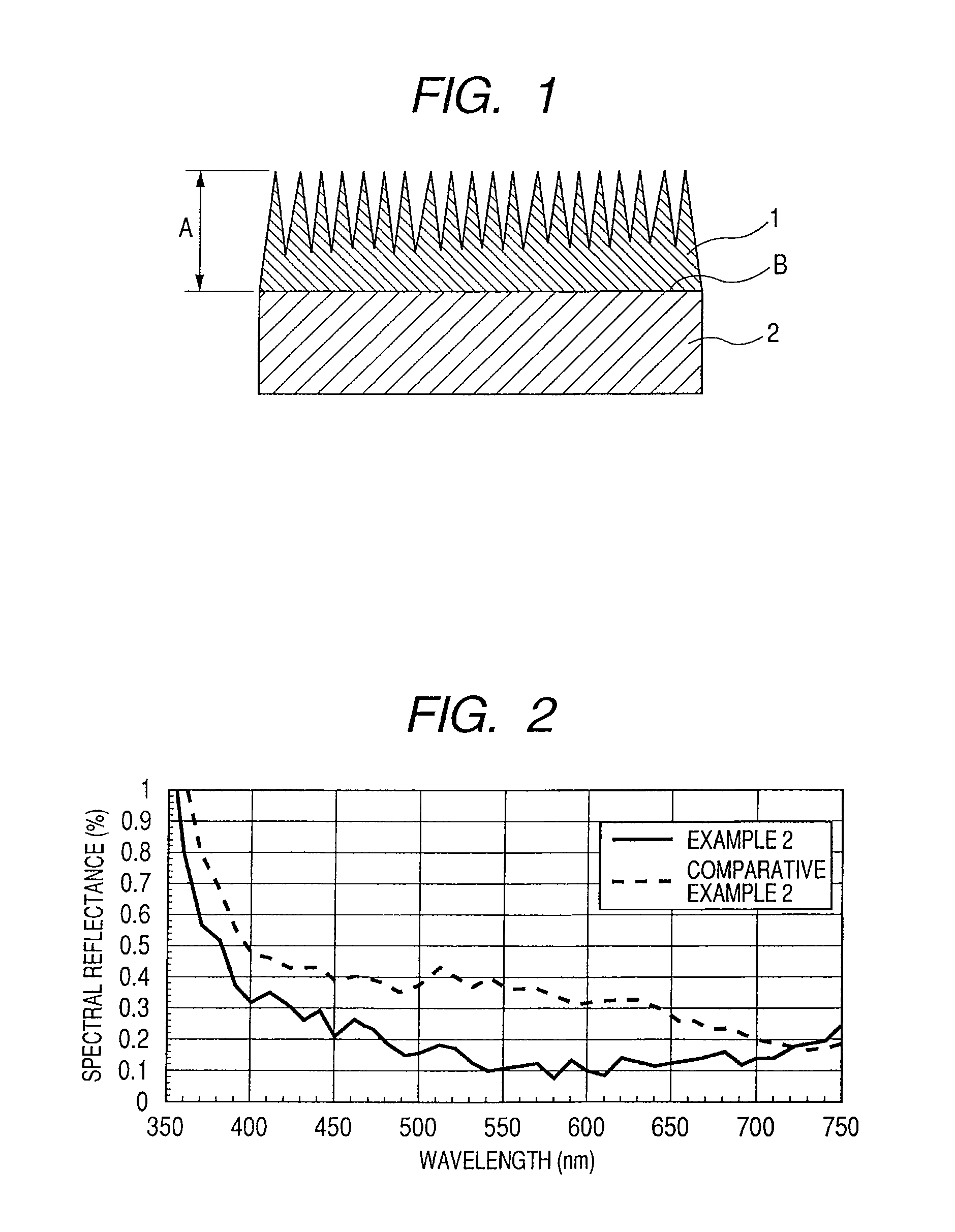
[0080]A quartz substrate having a reflection preventing film was fabricated and measured as in Example 1, except that the preliminary drying was carried out at 200° C. for 10 minutes and the heat treatment after the removal of the stabilizer was carried out at 200° C. for 2 hours. The results obtained are shown in Tables 1 and 2.

example 3

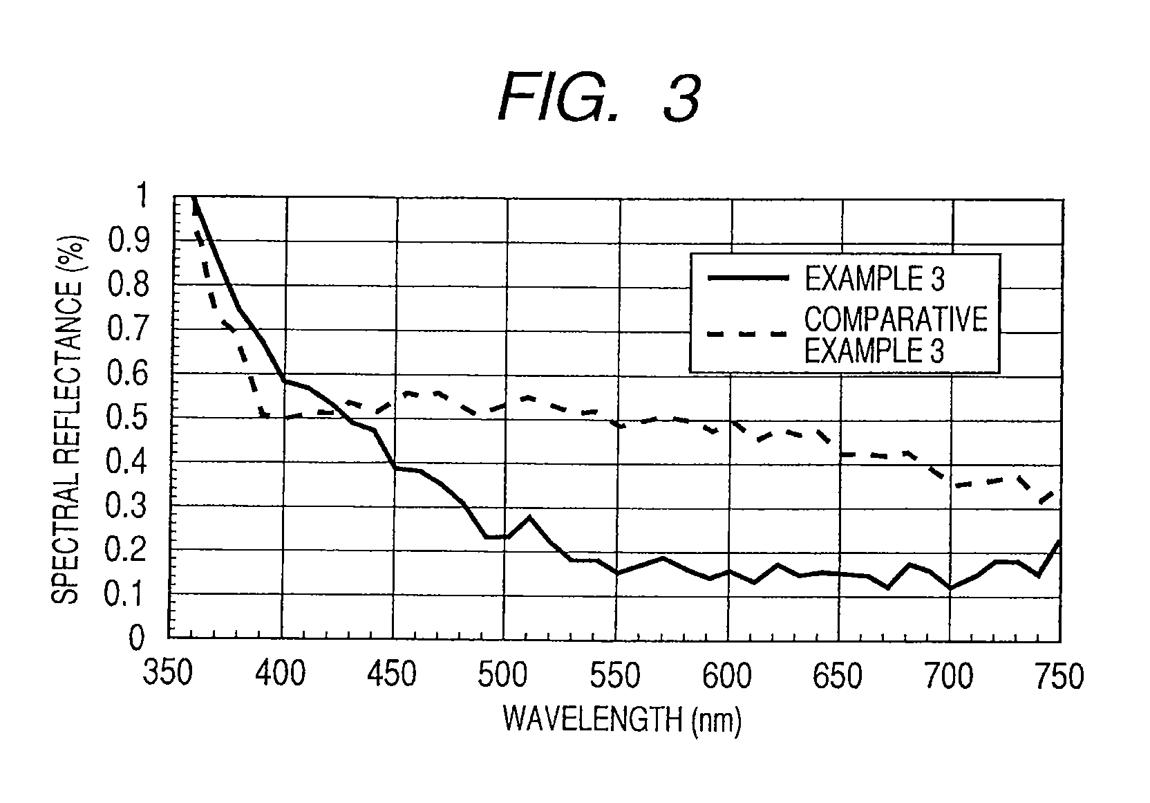
[0081]A quartz substrate having a reflection preventing film was fabricated and measured as in Example 1, except that the preliminary drying was carried out at 100° C. for 30 minutes and the heat treatment after the removal of the stabilizer was carried out at 100° C. for 3 hours. The results obtained are shown in Tables 1 and 2.


PUM

PropertyMeasurementUnit
transparencyaaaaaaaaaa
wavelengthaaaaaaaaaa
temperatureaaaaaaaaaa

Abstract

A method of manufacturing an optical element having a good reflection preventing characteristic is provided in which an irregularity structure having a reflection preventing function can be formed at low temperature. The method includes forming a film on the optical substrate by using a coating liquid containing a metal alkoxide containing at least aluminum, immersing the film in a water-containing liquid, baking the film having been immersed in the water-containing liquid, and subjecting the film having been baked to treatment with warm water to form an aluminum-containing film having a fine irregularity structure.

Description

[0001]This application is a division of application Ser. No. 12 / 130,073 filed May 30, 2008.BACKGROUND OF THE INVENTION[0002]1. Field of the Invention[0003]The present invention relates to a method of manufacturing an optical element having a function of suppressing the interface-reflected light amount, and to the optical element, and is suitable for optical elements of various types of optical devices including image pick-up devices such as cameras and video cameras, observation apparatuses such as telescopes and monocles, liquid crystal projectors, and optical scanning apparatuses of electrophotographic devices.[0004]The present invention can easily provide a fine irregularity structure having a reflection preventing function on the whole surface of an optical substrate, and can provide an optical element having a favorable reflection preventing characteristic at a low temperature without thermally damaging the optical element, and hence, can be utilized for optical substrates havi...

Claims


Application Information

Patent Timeline
Patent Type & Authority Patents(United States)
IPC IPC(8): B32B1/00B32B9/00C08J7/043C08J7/046
CPCC03C1/008C03C17/3417C03C17/007C03C2217/77Y10T428/24355Y10T428/31C03C2217/475C03C2218/113C03C2217/732C03C2217/73C03C2217/214C03C2217/465C03C2217/425C03C2218/116C03C2218/32C03C2217/477G02B1/113G02B1/118C08J7/043C08J7/046C08J7/06
Inventor TANAKA, HIROYUKIYAMADAKOTANI, YOSHINORI
Owner CANON KK
Learn More