
Process for removal of nitrogen and poly-nuclear aromatics from hydrocracker feedstocks

a technology of hydrocracking feedstock and nitrogen, which is applied in the direction of hydrocarbon oil cracking, chemistry apparatus and processes, organic chemistry, etc., can solve the problems of reducing the/or the quality of the products produced, and reducing the overall efficiency of the hydrocracking unit. achieve the effect of increasing the processing capacity of the hydrocracking uni

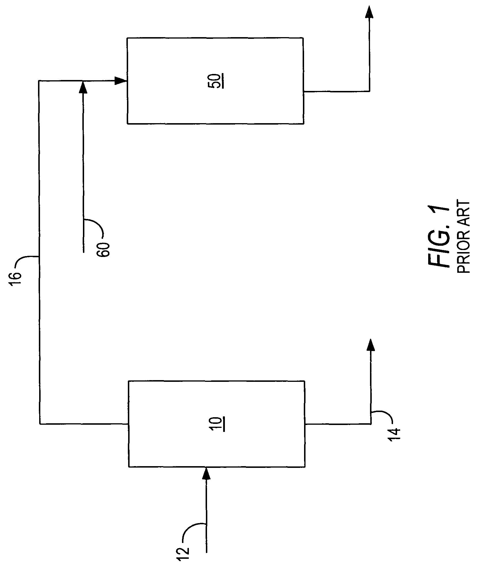
Active Publication Date: 2010-07-27
SAUDI ARABIAN OIL CO
View PDF35 Cites 110 Cited by
  • Summary
  • Abstract
  • Description
  • Claims
  • Application Information

AI Technical Summary

Benefits of technology

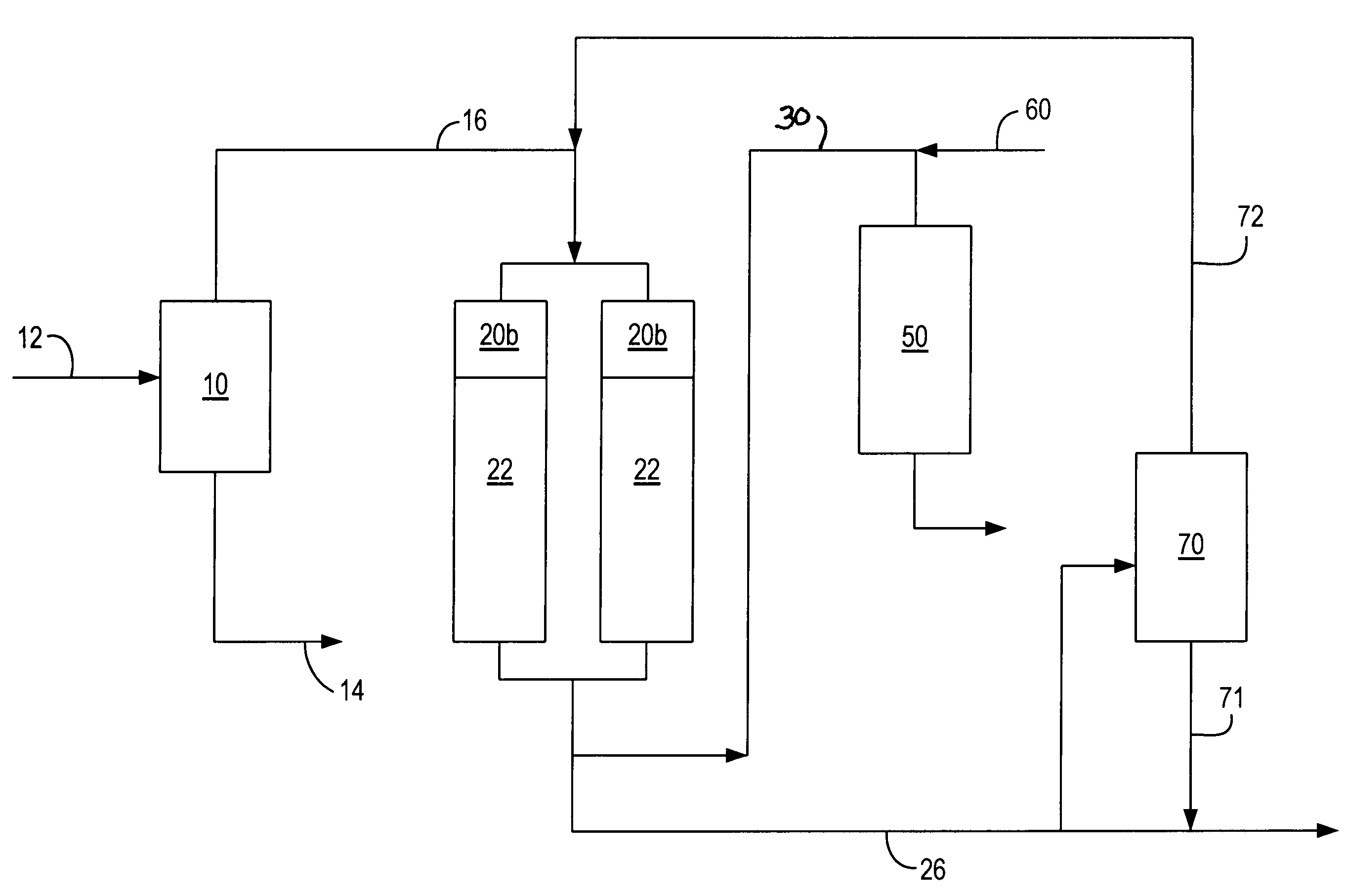
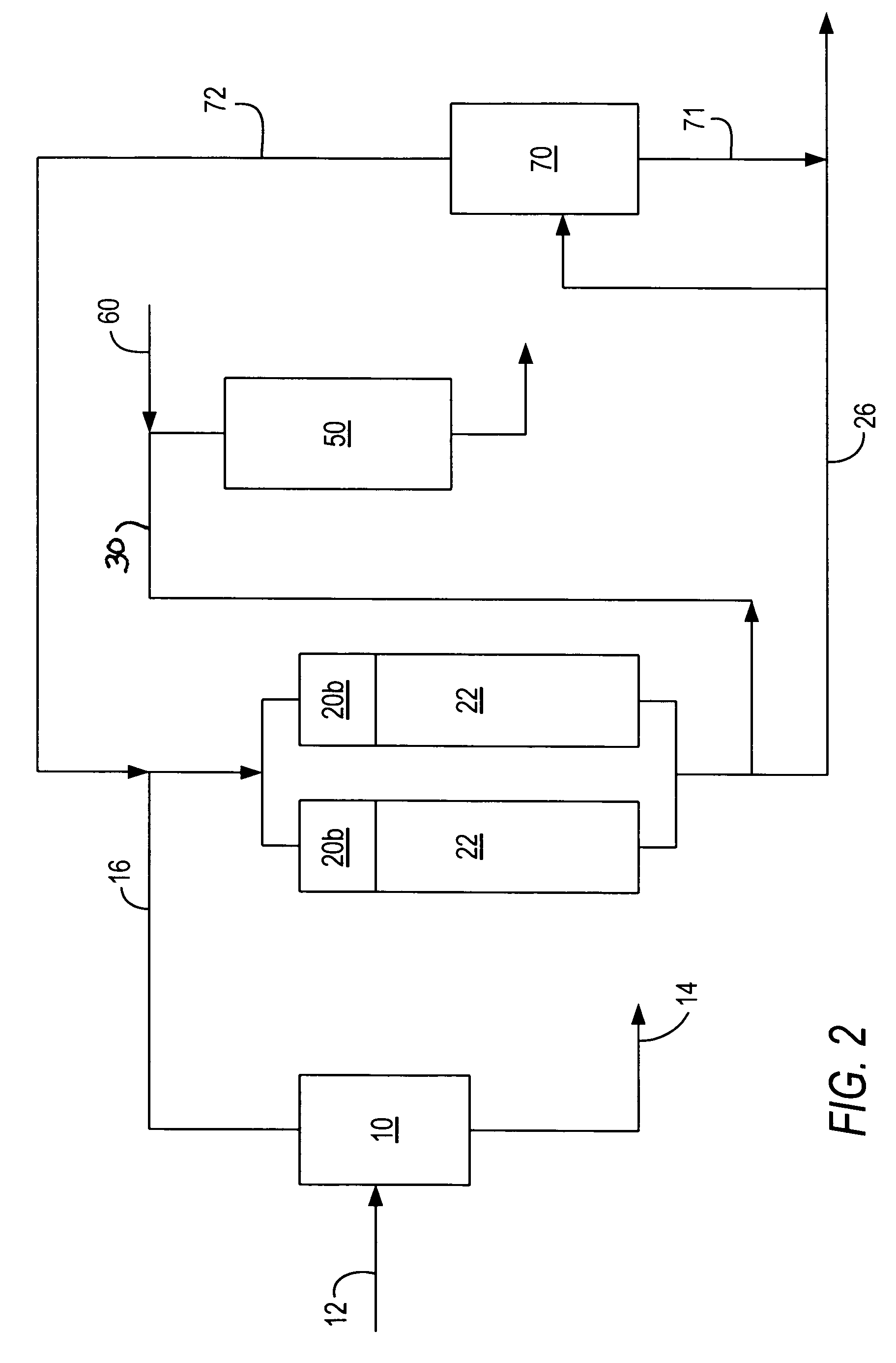
The present invention provides a process for treating heavy hydrocracking feedstocks to remove nitrogen-containing hydrocarbons and PNA compounds. This is achieved by passing the feedstock through a packed bed column or slurry column containing adsorbent material to absorb the nitrogen and PNA molecules. The cleaned feedstock is then sent to the hydrocracking unit or fluid catalytic cracking unit. The process is particularly useful for treating feedstocks from de-metalizing or solvent de-asphalting units, coking units, visbreaking units, and vacuum distillation units. The invention allows for the removal of nitrogen-containing compounds from the feedstock, which can be beneficial in other refinery processes.

Problems solved by technology

It is well known that the presence of nitrogen and poly-nuclear aromatics (“PNA”) in heavy oil fraction feedstocks have a detrimental effect on the performance of the hydrocracking unit.
Various processes have been proposed for removal of compounds that reduce the efficiency of the hydrocracking unit and / or the quality of the products produced.
The DMO or DAO in the blended feedstock to the hydrocracking unit can have the effect of lowering the overall efficiency of the unit, i.e., by causing higher operating temperature or reactor / catalyst volume requirements for existing units or higher hydrogen partial pressure requirements or additional reactor / catalyst volume for the grass-roots units.
These impurities can also reduce the quality of the desired intermediate hydrocarbon products in the hydrocracking effluent.

Method used


Image

  • Process for removal of nitrogen and poly-nuclear aromatics from hydrocracker feedstocks
  • Process for removal of nitrogen and poly-nuclear aromatics from hydrocracker feedstocks
  • Process for removal of nitrogen and poly-nuclear aromatics from hydrocracker feedstocks

Examples


example 1

De-Metalized Oil Pretreatment

[0044]Attapulgus clay with 108 m2 / g surface area and 0.392 cm3 / g pore volume was used as an adsorbent to remove nitrogen and PNA in a de-metallized oil stream. The virgin DMO contained 85.23 W % carbon, 11.79 W % hydrogen, 2.9 W % sulfur and 2150 ppmw nitrogen, 7.32 W % MCR, 6.7 W % tetra plus aromatics as measured by a UV method. The mid-boiling point of the DMO stream was 614° C. as measured by ASTM D-2887 method. The de-metallized oil is mixed with a straight run naphtha stream boiling in the range 36-180° C. containing 97 W % paraffins, the remainder being aromatics and naphthenes at 1:10 V:V % ratio and passed to the adsorption column containing Attapul gus clay at 20° C. The contact time for the mixture was 30 minutes. The naphtha fraction was distilled off and 94.7 W % of treated DMO was collected. The process reject 1 and 2 fractions yields, which were stripped-off from the adsorbent by toluene and tetrahydrofuran, respectively, were 3.6 and 2.3 ...

example 2

Vacuum Gas Oil Pretreatment

[0049]Attapulgus clay the properties of which are given in example 1 was also used as an adsorbent to remove nitrogen and PNA in a vacuum gas oil. The vacuum gas oil contained 85.40 W % carbon, 12.38 W % hydrogen, 2.03 W % sulfur and 1250 ppmw nitrogen, 0.33 W % MCR, 3.5 W % tetra plus aromatics as measured by UV method. The vacuum gas oil is mixed with straight run naphtha stream boiling in the range 36-180° C. containing 97 W % paraffins the remainder being aromatics and naphthenes at 1:5 V:V % ratio and passed to the adsorption column containing Attapulgus clay at 20° C. The contact time for the mixture was 30 minutes. The naphtha fraction was distilled off and 97.0 W % of treated VGO was collected. The process reject 1 and 2 fractions yields, which were stripped-off from the adsorbent by toluene and tetrahydrofuran, were 1.6 and 1.4 W % respectively. After the treatment process, 72 W % of organic nitrogen, 2 W % of sulfur, 10.9 W % of tetra plus aromat...

example 3

Heavy Diesel Oil Treatment

[0055]Heavy diesel oil containing 85.2 W % of carbon, 12.69 W % hydrogen, 1.62 W % of sulfur and 182 ppmw of nitrogen was subjected to the treatment process of the invention using an adsorption column at 20° C. at LHSV of 2 h−1. The pretreated heavy gas oil yield was 98.6 W %. The yield for the process reject fractions 1 and 2, which were stripped off by toluene and tetrahydrofuran, respectively, at a solvent-to-oil ratio of 4:1 V %, were 1.0 W % and 0.4 W %. The ASTM D2887 distillation curves for the heavy gas oil, treated heavy gas oil, reject 1 fraction which was desorbed from the adsorbent by toluene, and reject 2 fraction which is desorbed from the adsorbent by tetrahydrofuran, are shown in the Table below. The treatment process did not change the distillation characteristics of the heavy gas oil. The reject 1 and 2 fractions are heavy in nature with FBP 302 and 211° C. higher than that of the feedstock heavy gas oil. The process removes the heavy tail...


PUM

PropertyMeasurementUnit
temperatureaaaaaaaaaa

Abstract

A feedstream to a hydrocracking unit is treated to remove or reduce the content of polynuclear aromatics and nitrogen-containing compounds by contacting the feedstream with an adsorbent compound selected from attapulgus clay, alumina, silica gel and activated carbon in a fixed bed or slurry column and separating the treated feedstream that is lower in the undesired compounds from the adsorbent material. The adsorbent can be mixed with a solvent for the undesired compounds and stripped for re-use.

Description

[0001]This application is a continuation in-part of U.S. Ser. No. 11 / 584,771 filed Oct. 20, 2006 now U.S. Pat. No. 7,566,394.FIELD OF THE INVENTION[0002]The invention relates to the treatment of feedstocks to improve the efficiency of operation of hydrocracking or fluid catalytic cracking (FCC) units and the improvement of hydrocrackers and the effluent product streams of fluid catalytic cracking units.BACKGROUND OF THE INVENTION[0003]It is well known that the presence of nitrogen and poly-nuclear aromatics (“PNA”) in heavy oil fraction feedstocks have a detrimental effect on the performance of the hydrocracking unit. For example, in the operation of one refinery where the hydrocracker was fed by a de-metalized or de-asphalted stream included a high level of impurities such as nitrogen-containing compounds and PNA coming from a solvent de-asphalting unit were found to be present at 5-10% of the volume of the feedstock stream. The smoke point of kerosene product from the hydrocrackin...

Claims


Application Information

Patent Timeline
Patent Type & Authority Patents(United States)
IPC IPC(8): C10G67/06
CPCC10G25/00C10G25/06C10G55/06C10G67/06C10G25/003
Inventor KOSEOGLU, OMER REFA
Owner SAUDI ARABIAN OIL CO
Learn More