Flue gas control system of coal combustion boiler and operating method thereof
a technology of flue gas control system and coal combustion boiler, which is applied in the direction of machines/engines, electrostatic separation, water/sewage treatment by ion exchange, etc., can solve problems such as unsuitable treatment, and achieve the effect of reducing operating costs
- Summary
- Abstract
- Description
- Claims
- Application Information
AI Technical Summary
Benefits of technology
Problems solved by technology
Method used
Image
Examples
first embodiment
[0042]A flue gas control system of a coal combustion boiler according to a first embodiment of the present invention is explained with reference to the drawings.
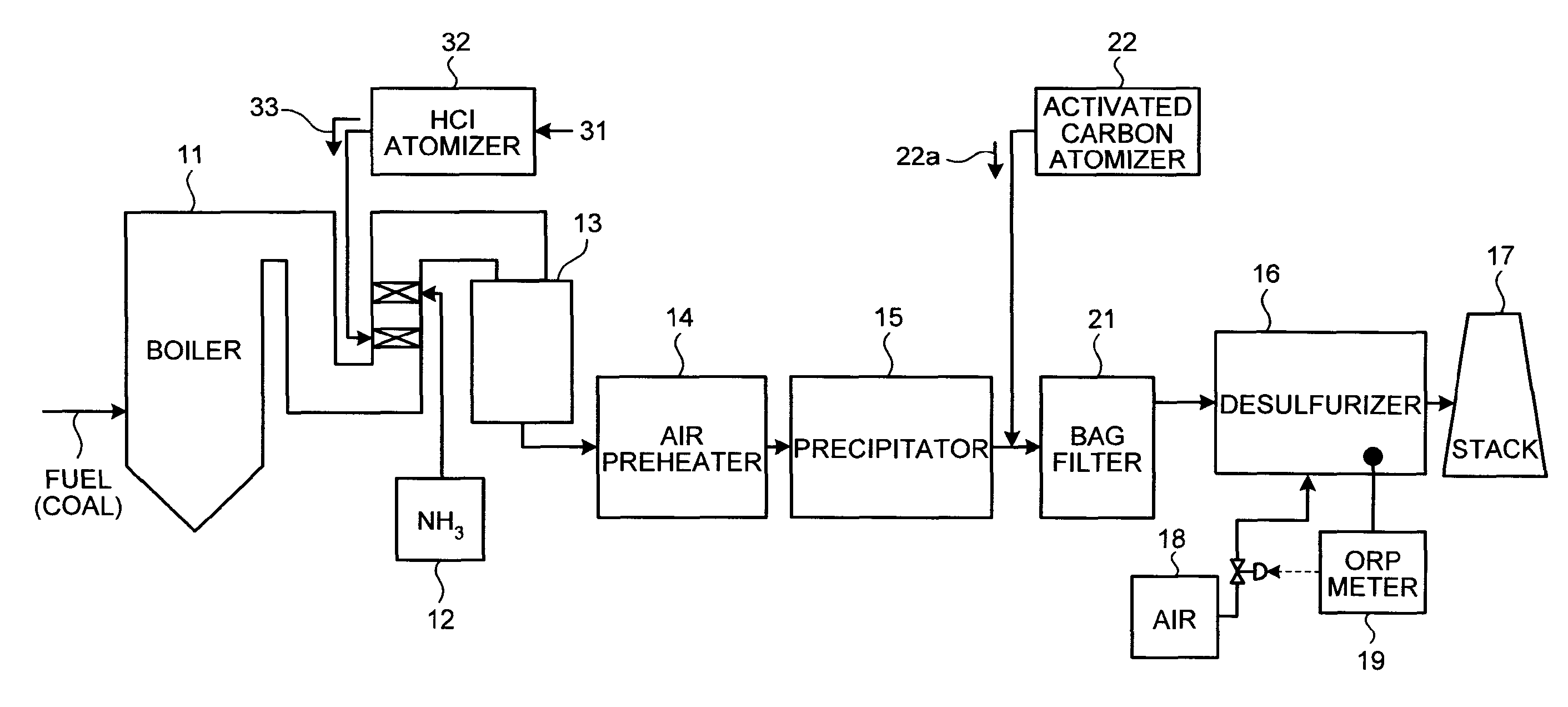
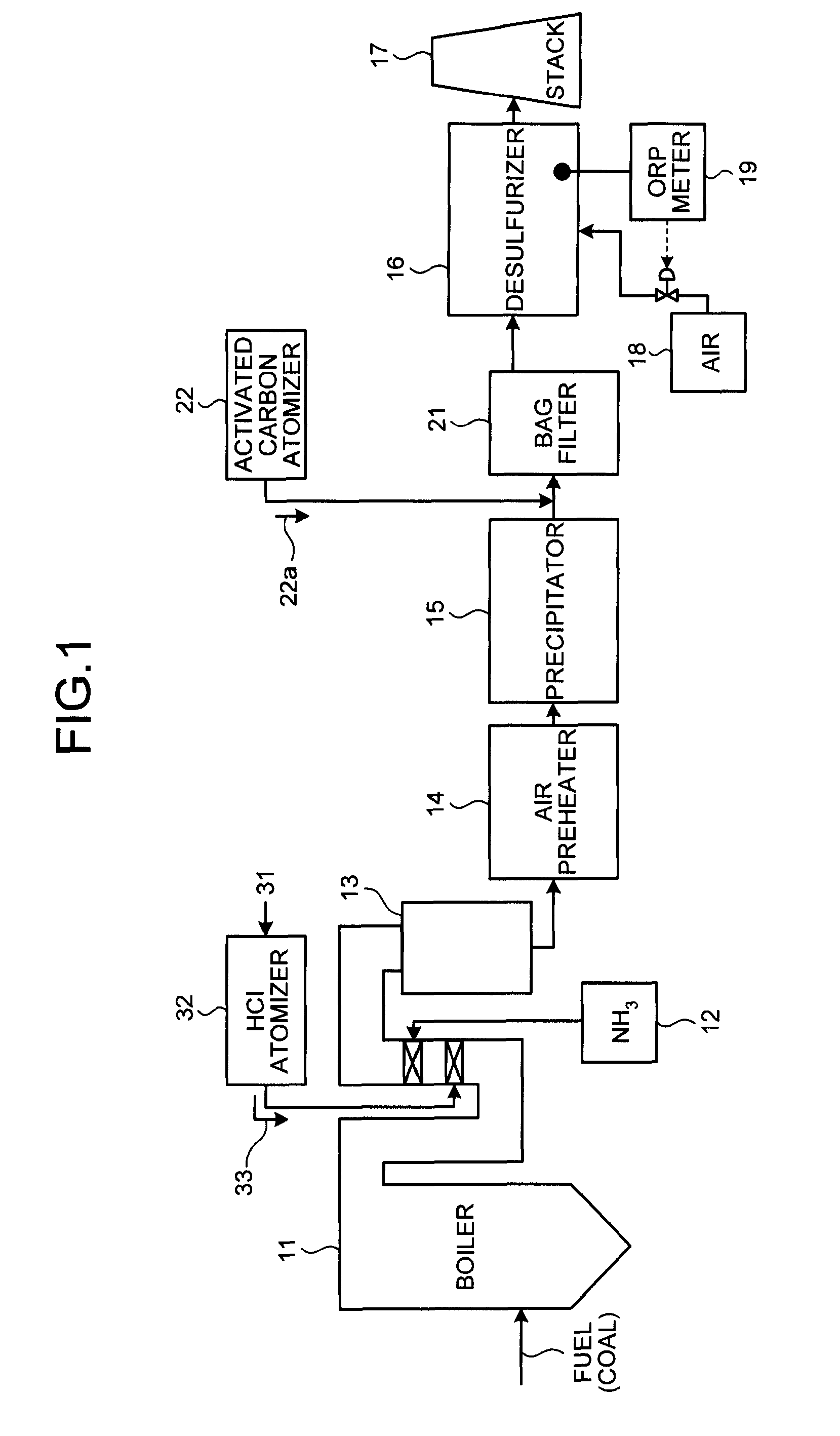
[0043]FIG. 1 is a schematic diagram of the flue gas control system of the coal combustion boiler according to the present invention.
[0044]The flue gas control system of the coal combustion boiler includes: an HCl atomizer 32 that sprays hydrogen chloride 33 to flue gas from the coal combustion boiler 11 that uses coal as a fuel F; the NOx removing apparatus 13 that removes nitrogen oxides by ammonia denitration by adding the ammonia 12 to the flue gas after spraying hydrogen chloride and oxidizes mercury; the air preheater 14 that recovers heat in the gas after removal of nitrogen oxides; the precipitator 15 that removes particulates in the gas after heat recovery; the activated carbon atomizer 22 that sprays activated carbon 22a into the gas after particulate collection; the bag filter 21 that collects activated carbon havi...
second embodiment
[0068]FIG. 5 is a schematic diagram of another flue gas control system of a coal combustion boiler according to the present invention.
[0069]The flue gas control system in this embodiment includes: the NOx removing apparatus 13 that removes nitrogen oxides in flue gas from the coal combustion boiler 11 by adding the ammonia 12 to the flue gas; the air preheater 14 that recovers heat in the gas after removal of nitrogen oxides; the precipitator 15 that removes particulates in the gas after heat recovery; the gas-liquid contact type desulfurizer 16 that removes sulfur oxides in the gas after particulate collection by a limestone gypsum method and also removes mercury oxides; and the stack 17 that discharges purged gas which has undergone desulfurization and mercury removal to outside. In this flue gas control system, a slurry absorbent containing mercury from the desulfurizer 16 is extracted to outside, a flocculant is added thereto before separating gypsum, thereby flocculating and re...
third embodiment
[0073]FIG. 6 is a schematic diagram of another flue gas control system of a coal combustion boiler according to the present invention.
[0074]The flue gas control system in this embodiment includes: the NOx removing apparatus 13 that removes nitrogen oxides in flue gas from the coal combustion boiler 11 by adding the ammonia 12 to the flue gas; the air preheater 14 that recovers heat in the gas after removal of nitrogen oxides; the precipitator 15 that removes particulates in the gas after heat recovery; the gas-liquid contact type desulfurizer 16 that removes sulfur oxides in the gas after particulate collection by the limestone gypsum method and also removes mercury oxides; and the stack 17 that discharges purged gas which has undergone desulfurization and mercury removal to outside. In this flue gas control system, a slurry absorbent containing mercury from the desulfurizer 16 is extracted to outside, the gypsum 24 is separated by the solid-liquid separator 41, supernatant water 23...
PUM
| Property | Measurement | Unit |
|---|---|---|
| oxidation reduction potential | aaaaa | aaaaa |
| molar ratio | aaaaa | aaaaa |
| heat | aaaaa | aaaaa |
Abstract
Description
Claims
Application Information
 - R&D
- Intellectual Property
- Life Sciences
- Materials
- Tech Scout
- Unparalleled Data Quality
- Higher Quality Content
- 60% Fewer Hallucinations
Browse by: Latest US Patents, China's latest patents, Technical Efficacy Thesaurus, Application Domain, Technology Topic, Popular Technical Reports.
© 2025 PatSnap. All rights reserved.Legal|Privacy policy|Modern Slavery Act Transparency Statement|Sitemap|About US| Contact US: help@patsnap.com


