
Handoff method comprising network control apparatus that receives data packets from both the core network and the other network control apparatus wherein said received data packets will be transformed into wireless data

a network control and data packet technology, applied in the direction of synchronisation arrangement, wireless commuication services, broadcast service distribution, etc., can solve the problems of communication being disconnected, waste of radio access network control apparatus resources, and inability to apply 3gpp schemes, etc., to reduce traffic and reduce line costs

Active Publication Date: 2010-07-06
PANASONIC INTELLECTUAL PROPERTY CORP OF AMERICA
View PDF11 Cites 6 Cited by
  • Summary
  • Abstract
  • Description
  • Claims
  • Application Information

AI Technical Summary

Benefits of technology

The present invention provides a method and system for reducing traffic and line cost during handover of a terminal in a wireless access network. The method involves detecting the entrance of the terminal into an area where it can communicate with another radio access network control apparatus, transmitting the wireless data from the original radio access network control apparatus to the new radio access network control apparatus, and receiving the wireless data at the new radio access network control apparatus. This allows for seamless communication with the portable terminal and reduces interruption during handover. The system includes a radio access network control apparatus and a portable terminal for implementing this method.

Problems solved by technology

However, if RLC Transparent Mode or Unacknowledge Mode is used, the 3GPP scheme can not be applied.
However, increasing the buffer size may waste resources in the radio access network control apparatus.
However, since it is required to start the measurement after the terminal is moved in order to measure appropriate delay time, the communication may be disconnected due to delay resulting from the measurement.
Further, in case of streaming, when overhead occurs in a communication between the source and target radio access network control apparatus, the transmission data is interrupted.

Method used


Image

  • Handoff method comprising network control apparatus that receives data packets from both the core network and the other network control apparatus wherein said received data packets will be transformed into wireless data
  • Handoff method comprising network control apparatus that receives data packets from both the core network and the other network control apparatus wherein said received data packets will be transformed into wireless data
  • Handoff method comprising network control apparatus that receives data packets from both the core network and the other network control apparatus wherein said received data packets will be transformed into wireless data

Examples


first embodiment

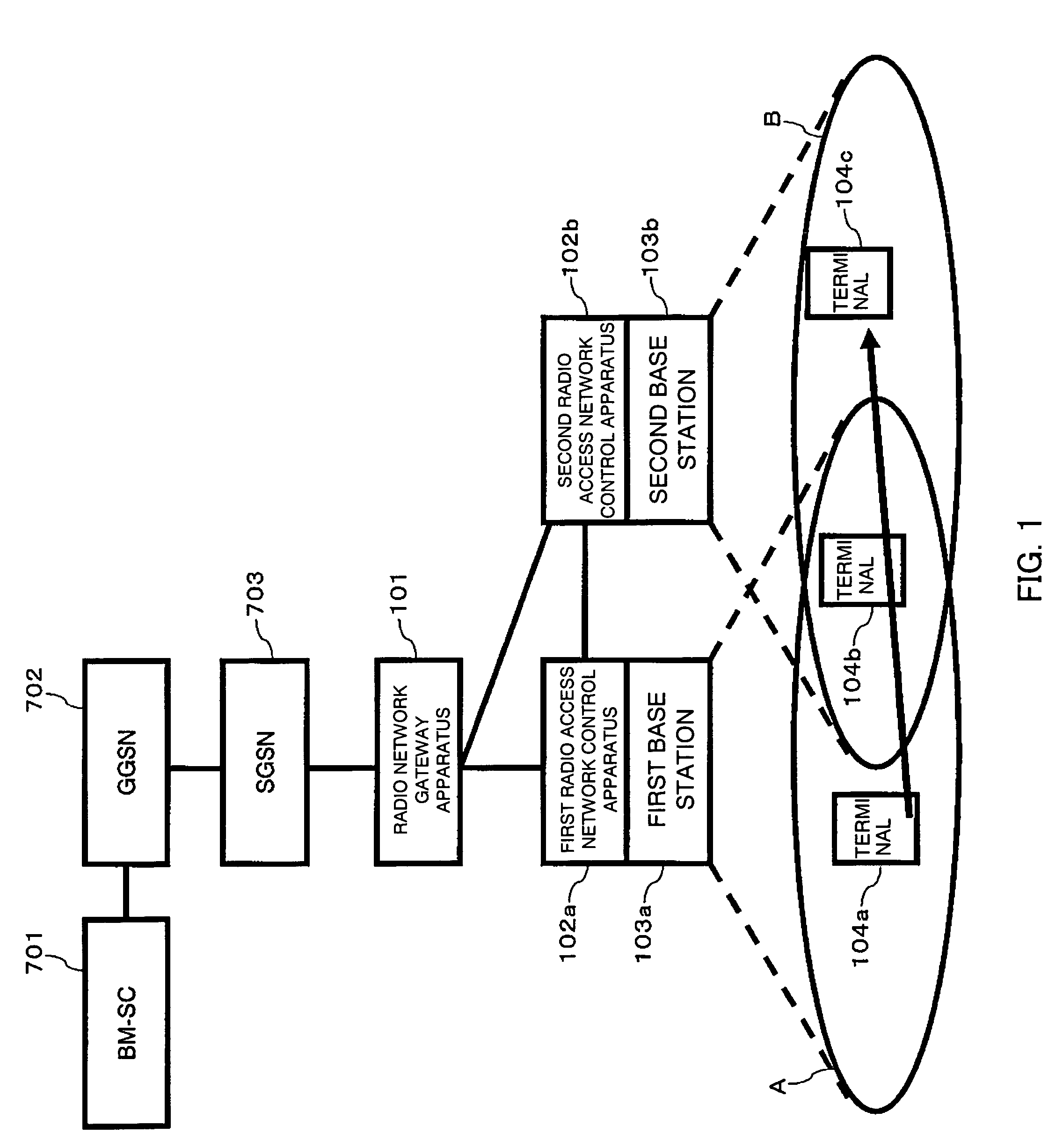
[0064]First, a summary of a first embodiment is described. In the present embodiment, traffic between a radio network gateway apparatus and a radio access network control apparatus is reduced by transmitting an MBMS packet from a source radio access network control apparatus to a radio access network control apparatus accommodating a terminal using MBMS as a Drift RNC.

[0065]A configuration of a system according to the present embodiment will be described below with reference to FIG. 1. Configurations of nodes BM-SC 701 to SGSN 703 are the same as those shown in FIG. 7 according to the prior art.

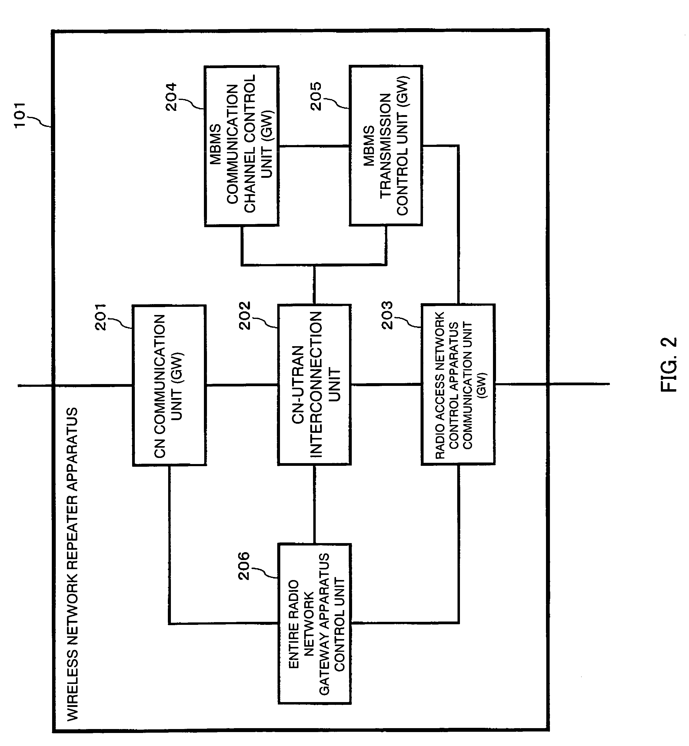
[0066]A radio network gateway apparatus 101 relays an MBMS packet in the same way as the prior art. In the present embodiment, the radio network gateway apparatus 101 recognizes a status of MBMS packet transmission between the radio access network control apparatus 102a and 102b in addition to the operations in the prior art. The first and second radio access network control apparatus 102a, 1...

second embodiment

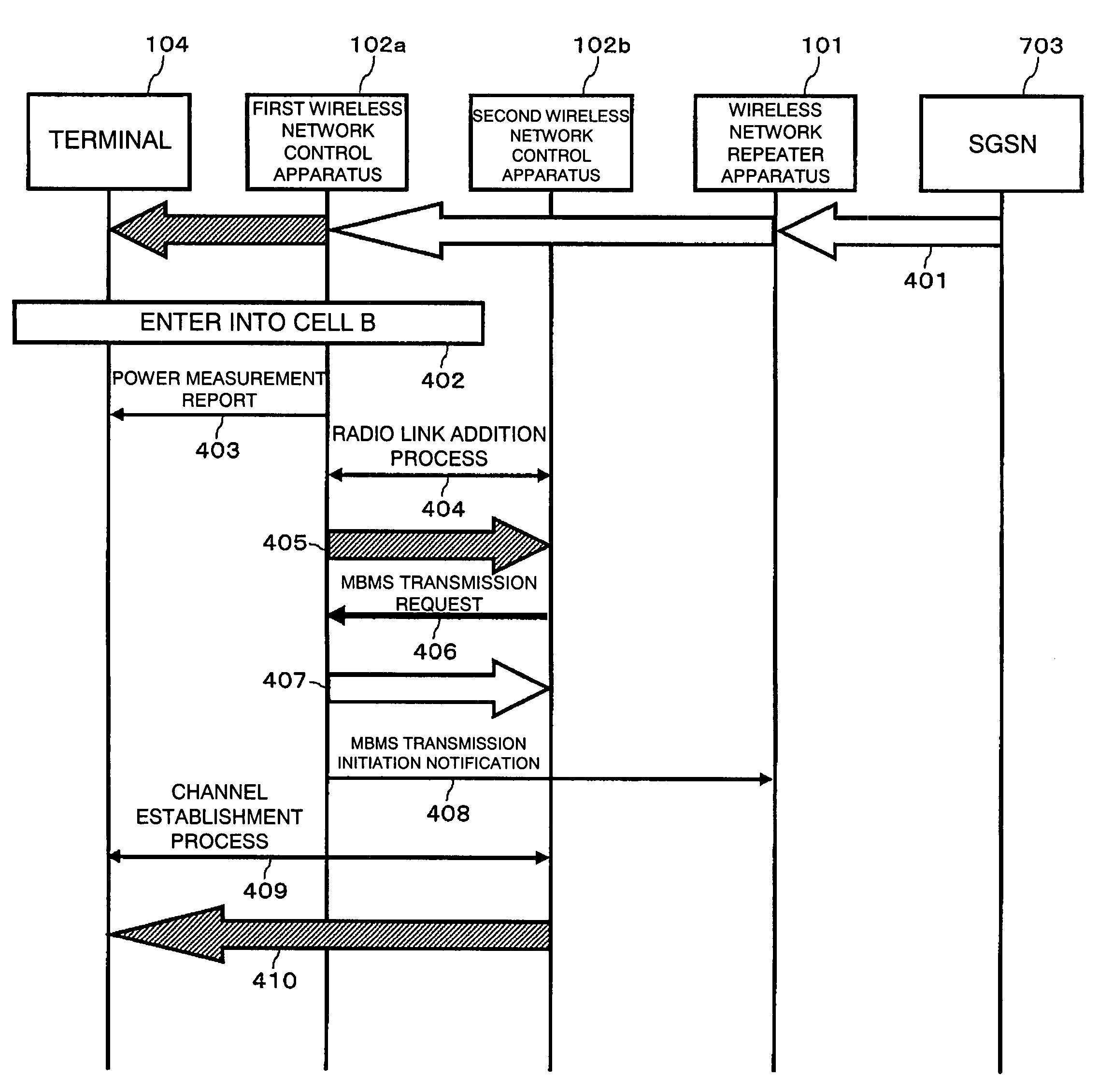
[0090]A second embodiment will be described below. First, a summary of the second embodiment is described. In the present embodiment, a method of reducing packet loss by synchronizing source and target channels during switching the connected radio access network control apparatus 102 after the terminal 104 is moved in the new cell B is illustrated.

[0091]FIGS. 5A to 5C show a summary of the switching method according to the present embodiment. In the present embodiment, a procedure, which is split into two steps, for switching from a transmission line via the radio access network control apparatus 102a to which the terminal 104c is connected to a transmission line via the radio access network control apparatus 102b for controlling the cell B to which the terminal 104c. FIG. 5A shows a state where the terminal 104c left the cell A and has just entered the cell B and FIGS. 5B and 5C show states after a first and second steps of the switching respectively.

[0092]In FIGS. 5A to 5C, compon...


PUM


Abstract

There are a wireless access network comprising a radio network gateway apparatus (101), radio access network control apparatus (102a), (102b) and a base stations (103a), (103b) and a terminal (104) accommodated in the wireless access network and when the terminal (104) enters into a new cell B, a packet data is transmitted from the source radio access network control apparatus (102a) to the target radio access network control apparatus (102b). Further, when the terminal (104) switches the radio access network control apparatus (102) with which the terminal (104) communicates, the target radio access network control apparatus (102b) switches a transmission line of a data to be transmitted to the terminal (104) from a wireless data to a packet data in the source radio access network control apparatus (102a), and from the source packet data to a target packet data in a synchronized manner at each timing. This reduces traffic which occurs when switching a radio access network control apparatus to be communicated while the terminal moves between cells and prevent packet interruption in a wireless access network providing packet transmission service.

Description

TECHNICAL FIELD[0001]The present invention relates to a method of switching radio access network control apparatus which maintains a communication when a terminal moves between cells while, for example, a service using multicast is provided in a wireless access network of a mobile communication system.BACKGROUND ART[0002]Currently, mobile telephones have been found in the fields that require more bandwidth such as access to WWW and videophone in addition to audio. There is increasing demand for bandwidth. In response to this, so-called third generation schemes such as W-CDMA (Wideband Code Division Multiple Access) and MC-CDMA (Multicarrier CDMA) schemes are being introduced. Further, MBMS (Mobile Broadcast / Multicast Service) providing a multicast service are being standardized in 3GPP (3rd Generation Partnership Project).[0003]FIG. 7 shows a configuration of a W-CDMA wireless access network according to the prior art. This configuration is disclosed, for example, in Japanese Patent...

Claims


Application Information

Patent Timeline
Patent Type & Authority Patents(United States)
IPC IPC(8): H04W36/00H04L12/28H04L45/80H04W4/06H04W36/10H04W36/38H04W40/34H04W56/00H04W92/14H04W92/22
CPCH04W36/10H04W92/14H04W92/22H04W36/0007
Inventor ISHII, HIDENORITAKAGI, KENJI
Owner PANASONIC INTELLECTUAL PROPERTY CORP OF AMERICA
Learn More