
Arrangement for cooling SMD power components on a printed circuit board

a technology of printed circuit board and power components, which is applied in the direction of cooling/ventilation/heating modification, electrical equipment, heat exchange equipment, etc., can solve the problems of increasing the manufacturing cost of printed circuit board, likewise involving the manufacture of thermal vias, and the dependence of heat dissipation by natural convection on the mounting position, so as to achieve the effect of simple and inexpensive manufacturing, and less dependence on the mounting position

Inactive Publication Date: 2010-06-29
SIEMENS AG OESTERR
View PDF13 Cites 17 Cited by
  • Summary
  • Abstract
  • Description
  • Claims
  • Application Information

AI Technical Summary

Benefits of technology

"The present invention is about a cooling arrangement for SMD power components that is less dependent on mounting position and is simple and inexpensive to manufacture. The arrangement includes a heat sink with heat dissipating elements oriented obliquely to the printed circuit board. The heat dissipating elements can be easily manufactured as bent sheet-metal parts, which can be soldered to a heat conducting or heat distributing layer on which the component to be cooled is mounted. The heat sink elements can be planar or finger-shaped, and can form an acute angle with the board-shaped mounting substrate for efficient heat dissipation. The heat sink elements can be adjacent to the sides of the cuboidal SMD power component or can be soldered in place. The invention is advantageous for manufacturing in SMD technology and is cost-effective."

Problems solved by technology

The provision of thermal vias likewise constitutes an increased printed circuit board manufacturing cost.
These known heat removal concepts are costly in manufacturing terms and also have the disadvantage that heat dissipation by natural convection is dependent on the mounting position.
Under worst case conditions a hot spot may occur which can impair the operational capability of the SMD circuit.

Method used


Image

  • Arrangement for cooling SMD power components on a printed circuit board
  • Arrangement for cooling SMD power components on a printed circuit board
  • Arrangement for cooling SMD power components on a printed circuit board

Examples


Embodiment Construction

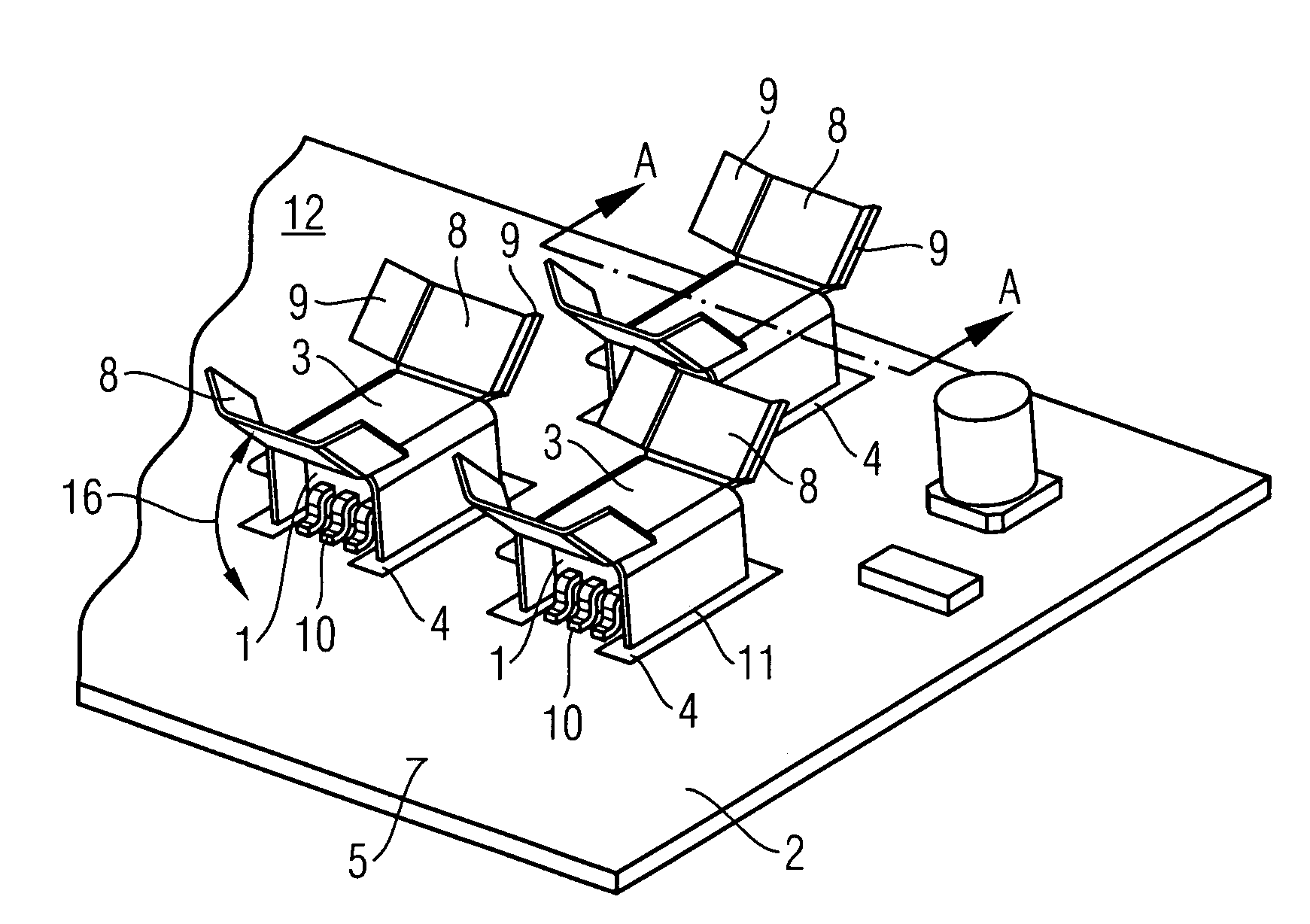
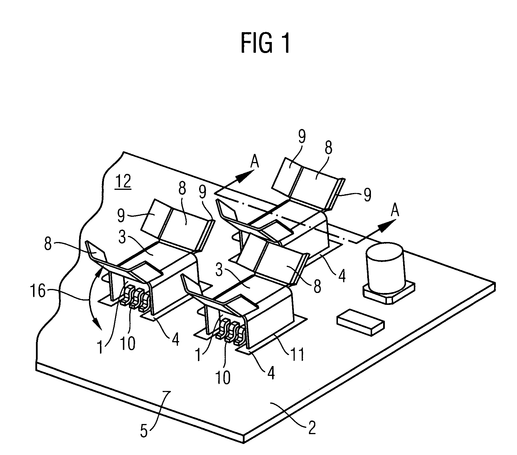
[0024]FIG. 1 shows an example of the inventive cooling arrangement, as used for a dimmer control in electrical installations (EIB bus).

[0025]Power components 1 are surface-mounted on a component side 5 of a printed circuit board 2. These SMD components have terminal contacts 10 which are electrically connected to conductor tracks not shown in greater detail here. Each SMD power component 1 in FIG. 1 is mounted in a thermally conductive manner on a heat conducting or distributing layer 4 which is implemented on the mounting surface 5, the thermally conductive layer 4 having the shape of a double-T. A U-shaped heat sink 3 disposed on the same side of the mounting substrate 2 as the components 1 forms a kind of tunnel around each of these SMD power components 1. The heat sink 3 is formed from a copper sheet in one piece. This bent sheet-metal part is preferably made by punch-bending.

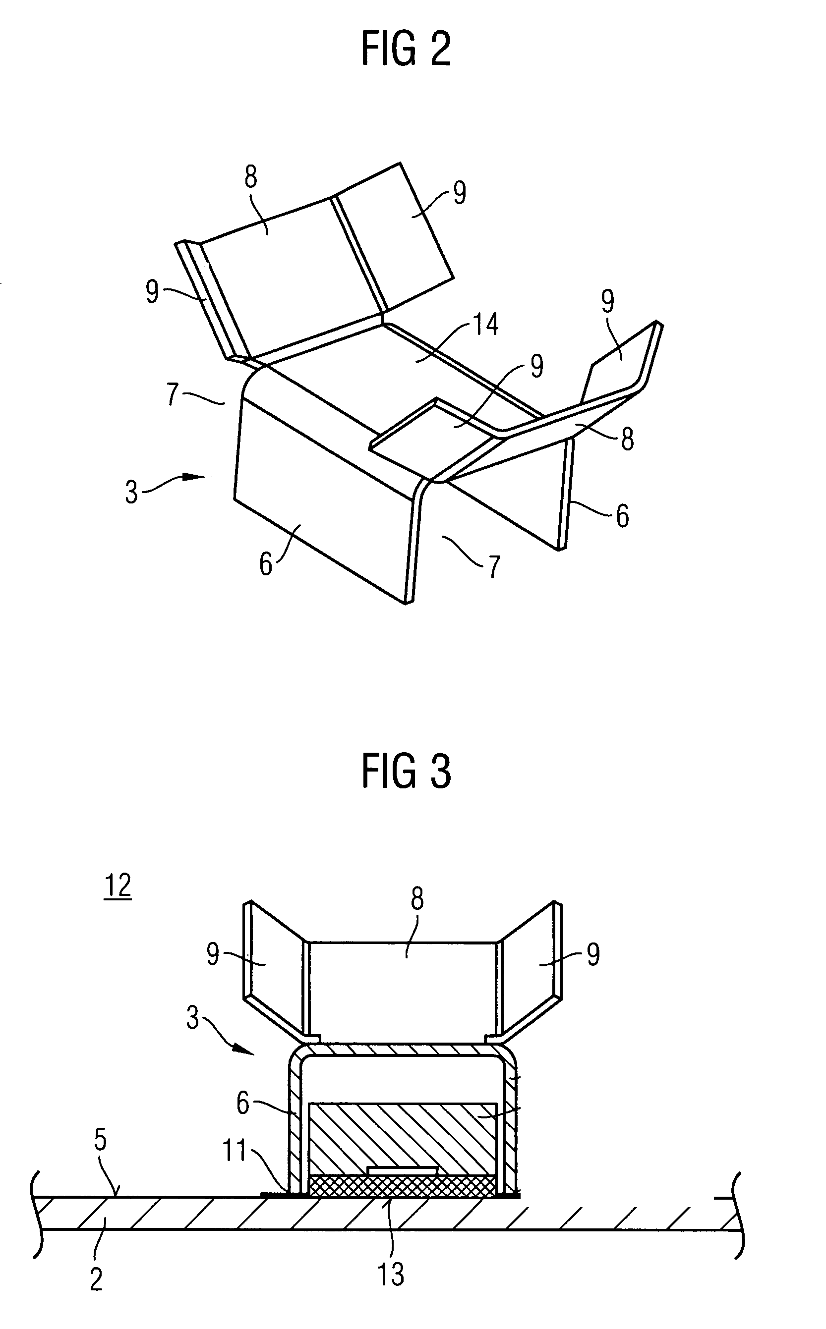
[0026]FIG. 2 shows this bent sheet-metal part 3 separately in a 3D drawing. It essentially consists of a...


PUM


Abstract

There is described an arrangement for cooling electrical components disposed on a board-shaped mounting substrate, particularly SMD power components on a printed circuit board, wherein at least one heat sink assigned to a component is present which is disposed on the same side as the components and which is connected in a thermally conductive manner to the assigned component by means of a thermally conductive layer implemented on the mounting substrate. The heat sink is implemented as a bent sheet-metal part and is connected to the thermally conductive layer by means of a solder joint, wherein the bent sheet-metal part has at least one heat sink element which extends in a longitudinal direction and said longitudinal direction is oriented obliquely to the plane of the board-shaped substrate.

Description

CROSS REFERENCE TO RELATED APPLICATIONS[0001]This application claims priority of Austrian application No. A846 / 2006 filed May 5, 2004, which is incorporated by reference herein in its entirety.FIELD OF INVENTION[0002]The invention relates to an arrangement for cooling components disposed on a board-shaped mounting substrate, in particular SMD (Surface Mount Device) power components on a printed circuit board, there being at least one heat sink which is disposed on the component side and which is connected in a thermally conductive manner to an associated component by means of a thermally conductive layer implemented on the mounting substrate.BACKGROUND OF INVENTION[0003]Various heat dissipation concepts for cooling power components mounted using surface mount technology (SMT) are known. The heat can be dissipated by heat sinks which are disposed either on the component side or on the back of the printed circuit board.[0004]DE 43 32 115 B4 discloses a printed circuit board cooling ar...

Claims


Application Information

Patent Timeline
Patent Type & Authority Patents(United States)
IPC IPC(8): H05K7/20F28F7/00H01L23/34H01L23/26
CPCH01L23/3672H01L23/467H05K7/205H01L2924/0002H01L2924/00
Inventor HELLINGER, LEOPOLDNEUMANN, GERHARD
Owner SIEMENS AG OESTERR
Learn More