
N-phase ozone generator

a generator and ozone technology, applied in the direction of oxygen/ozone/oxide/hydroxide, electrical discharge ozone preparation, dc-ac conversion without reversal, etc., can solve the problem of large discharge capacity, difficult to disperse silent electric discharge over a large discharge area uniformly and steadily, and large system size of large-capacity ozone generators, etc. problem, to achieve the effect of low cost, high ozone yield and improved load power factor

Active Publication Date: 2010-06-29
TOSHIBA MITSUBISHI-ELECTRIC IND SYST CORP
View PDF16 Cites 2 Cited by
  • Summary
  • Abstract
  • Description
  • Claims
  • Application Information

AI Technical Summary

Benefits of technology

The present invention relates to a large-capacity ozone generator that can generate ozone at a high rate for advanced sewage treatment and pulp bleaching. The invention is a n-phase ozone generator that uses an n-phase AC power supply and electrically divides the ozone generation cells into n discharge cells. The generator has a high power supply capacity and a low load power factor, making it suitable for large-scale applications. The technical effects of the invention include improved ozone generation efficiency, reduced energy consumption, and improved load power factor.

Problems solved by technology

Therefore, it is difficult to disperse a silent electric discharge over a large discharge area uniformly and steadily.
Since the power factor of the ozone generator is as low as 30% at an operating frequency of 1 kHz, the discharge capacity is extremely large.
Consequently, the large-capacity ozone generator is a huge system.
Consequently, a large amount of ozone gas is obtained.
As indicated by characteristic region 8002a for the multi-layer flat-plate type, the use of a large-capacity ozone generator remarkably reduces the discharge resistance of the ozone generator and makes it difficult to disperse a discharge over the entire surface and generate stable ozone.
As a result, it is found that the use of a large-capacity ozone generator in place of a small-capacity ozone generator cannot obtain high-concentration ozone and reduces the ozone yield.
An increase in the single unit capacity results in a poor discharge power factor and increases the peak current for the load current value.
It means that an economical limit is imposed due, for instance, to an increase in the power consumption for ozone generation.
Consequently, the single unit capacity of the ozone generator is limited.
Furthermore, an increase in the single unit capacity remarkably reduces the discharge cell load impedance.
It means that the power supply control capability for stable supply of generated ozone is extremely degraded.
As a result, various problems, including the inability to increase the single unit capacity, have arisen.

Method used


Image

  • N-phase ozone generator
  • N-phase ozone generator
  • N-phase ozone generator

Examples


first embodiment

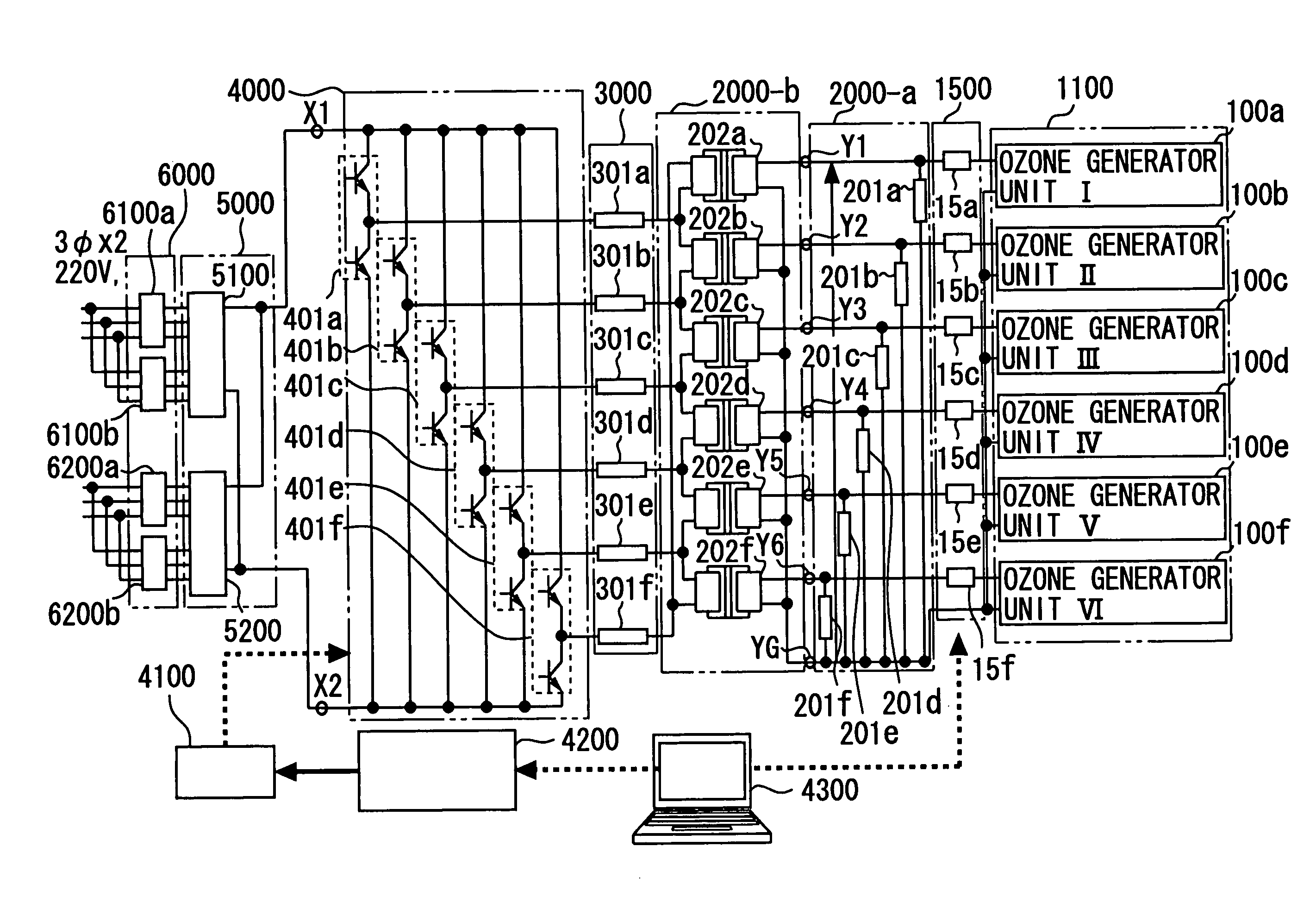
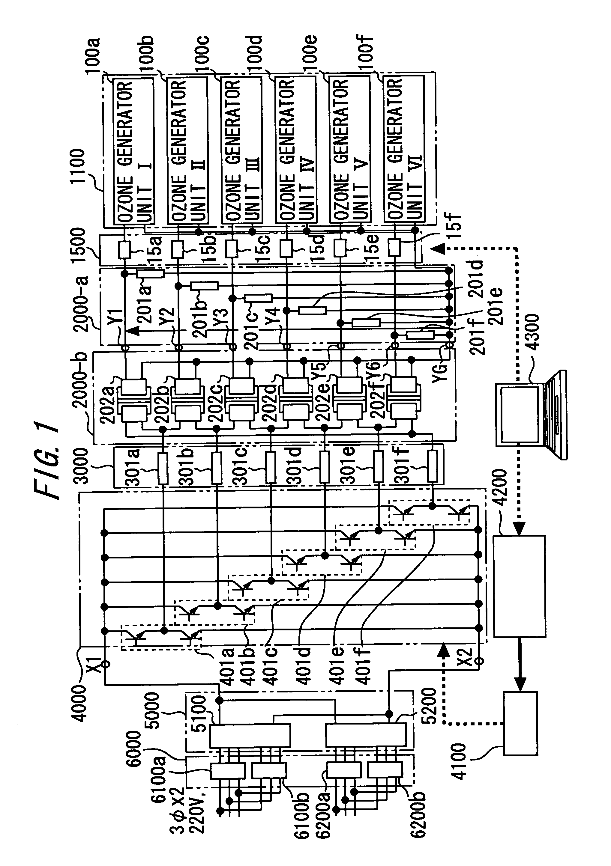
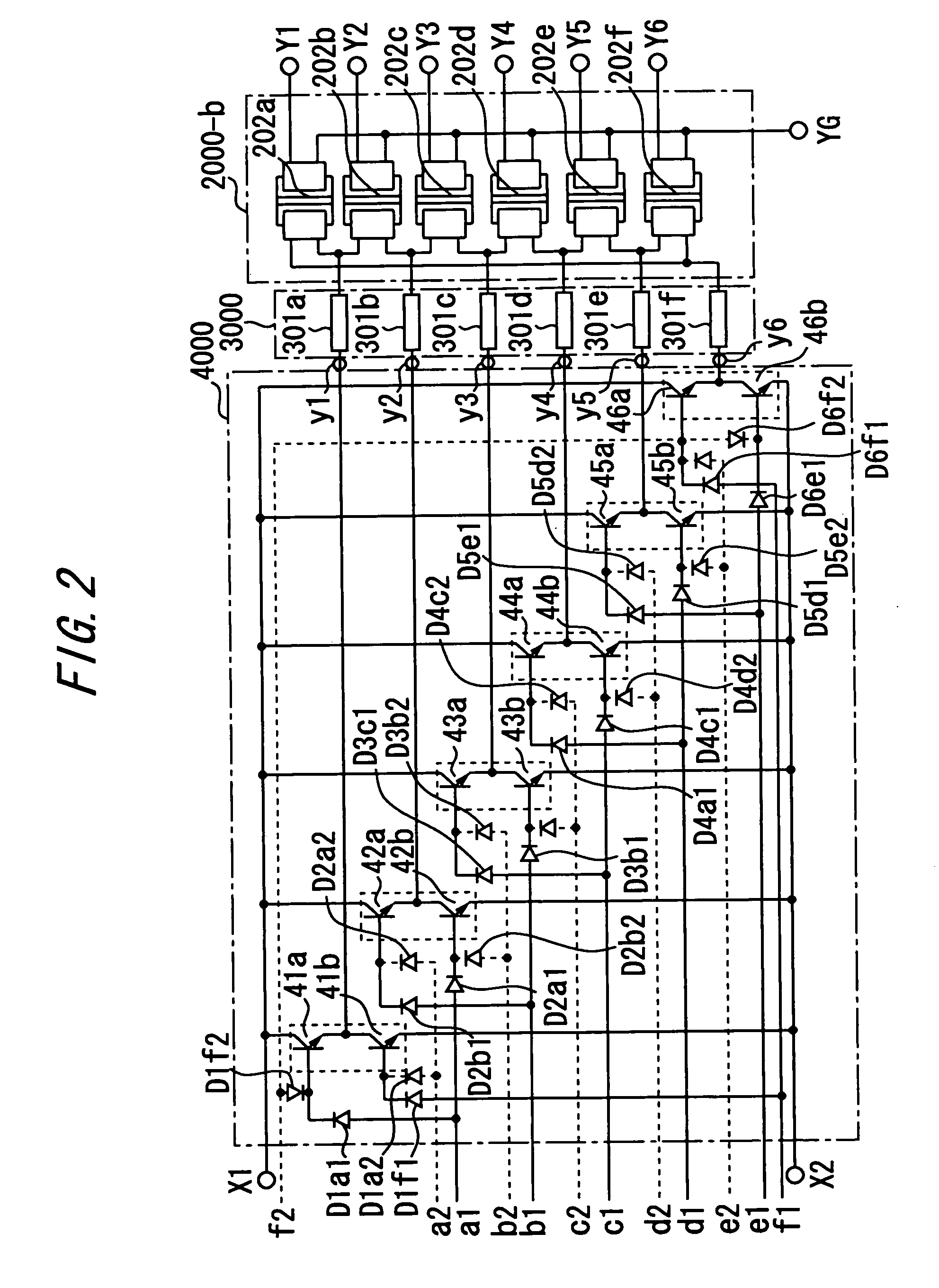
[0095]FIG. 1 is a schematic circuit diagram illustrating the overall system of an n-phase ozone generator that comprises a 6-phase inverter, reactor, and 6-phase transformer in accordance with a first embodiment of the present invention. FIG. 2 is a diagram illustrating a main circuit and gate signal circuit of an n-phase inverter according to the first embodiment of the present invention. FIG. 3 is a detailed system configuration diagram illustrating various components of the n-phase ozone generator according to the first embodiment of the present invention. FIG. 4 is a characteristics diagram illustrating an instruction signal and inverter output waveform of an n-phase inverter according to the present invention.

[0096]FIG. 3 excludes a converter unit 5000 and an input transformer 6000, which are shown in FIG. 1.

[0097]In FIGS. 1 to 3, the reference numerals 100a-100f denote six ozone generator units, and the reference numeral 1100 denotes a 6-phase (n-phase) ozone generator that co...

second embodiment

[0104]In a second embodiment of the present invention, the parallel reactor block 2000-a includes six (n) reactors that are identical with each other. The parallel reactor block 2000-a is connected between the high-voltage side and low-voltage potential (ground) of the secondary side of the 6-phase (n-phase) transformer block 2000-b. The reactors 201a-201f are inserted into the ozone generator units 100a-100f in a parallel manner. The load on the ozone generator units 100 is a capacitance load because it is made of a dielectric. The load is a leading load. The power factor is as low as approximately 20%. Therefore, if, for instance, the employed design is such that a power of 10 kW is supplied to the ozone generator units 100, it is necessary that a power of approximately 50 kVA be supplied to each ozone generator unit 100 because the power factor is low. In other words, the design requirements are such that the transformer block 2000-b and inverter block 4000 have large capacities....

third embodiment

[0107]A third embodiment of the present invention will now be described with reference to FIG. 5. The third embodiment includes a time division device that is capable of equally dividing the time into 3 to n phases. When a designated phase count signal is entered into the time division device from the outside, the time division device issues an equally-time-divided signal to the inverter. Variable control can then be exercised for an arbitrary phase while maintaining balance gradually for 3 to n phases.

[0108]As indicated in FIG. 5, the computer 4300 enters the ozone generator frequency F and the number n of phases to be driven by the inverter. The computer 4300 calculates the intervals T for the inverter element block 4000 and the phase time t from entered n phases. Further, the computer 4300 calculates an inverter drive instruction for all phases of the inverter elements 401 via the control circuit 4200 and inverter drive circuit 4100.

[0109]Referring to FIG. 5, the reference numera...


PUM


Abstract

A compact, inexpensive, large-capacity ozone generator with increased ease of apparatus maintenance. An ozone power supply includes an n-phase inverter for obtaining an AC voltage having a predetermined frequency and outputting an n-phase AC voltage waveform; n reactors and an n-phase transformer for converting an n-phase AC voltage to a high AC voltage; n high-voltage terminals for outputting the n-phase high AC voltage; and a low-voltage terminal having a common potential. Ozone generator units are electrically divided into n pieces within a discharge chamber. Each ozone generator unit includes n high-voltage electrode terminals and one low-voltage electrode terminal, common to all ozone generator units. Each ozone generator unit supports an n-phase AC discharge to generate ozone.

Description

TECHNICAL FIELD[0001]The present invention relates to a large-capacity ozone generator for receiving a material gas supply based on oxygen and generating an ozone gas, and more particularly to an n-phase ozone generator having an n-phase AC power supply configuration for an ozone power supply and a configuration for electrically dividing ozone generator discharge cells into n discharge cells (ozone generation units).BACKGROUND ART[0002]A conventional large-capacity ozone generator is typically configured as shown in FIG. 10 to construct a several-tens-to-several-hundreds-of-kilograms-per-hour class, large-capacity ozone generator. This large-capacity ozone generator is adopted to use ozone for advanced sewage treatment and pulp bleaching.[0003]FIG. 10 shows an example of a conventional, large-capacity ozone generator that generates ozone at a rate of 35 kg / h. The conventional large-capacity ozone generator 1100 includes a water tank for cooling, a huge tank (3000 mm in diameter and ...

Claims


Application Information

Patent Timeline
Patent Type & Authority Patents(United States)
IPC IPC(8): B01J19/08
CPCC01B13/115H02M7/48C01B2201/12C01B2201/40C01B2201/84C01B2201/90C01B2201/76
Inventor TABATA, YOICHIROOKIHARA, YUJIROISHIKAWA, MASAYUKISAITSU, TETSUYA
Owner TOSHIBA MITSUBISHI-ELECTRIC IND SYST CORP
Learn More