
System and method for maintaining a constant processor service level in a computer

a technology of computer system and service level, applied in the field of data processing systems, can solve the problems of intolerant businesses to the loss of computer equipment service, the loss of computerized telephony equipment can slow down or shut down business operations, and the processor within the critical equipment cannot be disabled, so as to achieve the effect of maintaining processor performan

Active Publication Date: 2010-06-08
UNISYS CORP
View PDF12 Cites 9 Cited by
  • Summary
  • Abstract
  • Description
  • Claims
  • Application Information

AI Technical Summary

Benefits of technology

[0008]An embodiment of the invention includes a method of maintaining processor performance in a computer system having at least two processors. The multiprocessor environment allows recovery of a disabled processor by either or both of two techniques; a dynamic processor recovery and automatic execution rate regulation.

Problems solved by technology

Many businesses are intolerant to the loss of service in computer equipment that provides services to their business or customers.
Loss of computerized telephony equipment can slow down or shut down business operations until a serviceman or other trained specialist can recover the computerized system to full operation.
Service loss, even partial loss, could be the result of a hardware or software fault resulting in a disabled processor within the critical equipment.
In systems with multiple processors, loss of a single processor can adversely affect the ability of the business to maintain service levels to their employees or customers.
Often, manual equipment operator intervention is needed to recover those systems when a processor becomes disabled.
But this redundancy switching can sometimes require manual intervention.
Additionally, if redundancy is not available, then functionality may simply be lost or seriously degraded until the equipment is repaired or replaced.

Method used


Image

  • System and method for maintaining a constant processor service level in a computer
  • System and method for maintaining a constant processor service level in a computer
  • System and method for maintaining a constant processor service level in a computer

Examples


Embodiment Construction

Partitioned Computer Environment

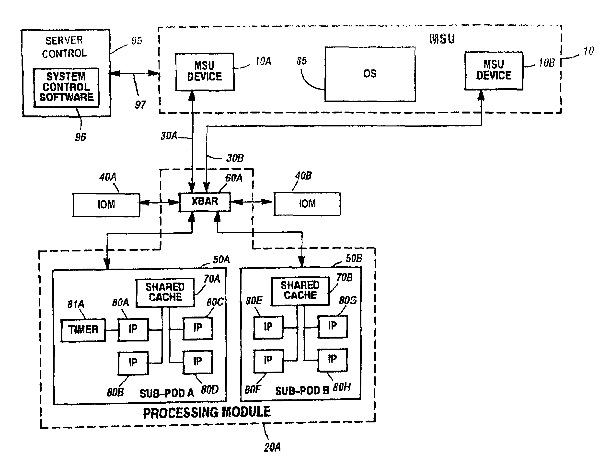
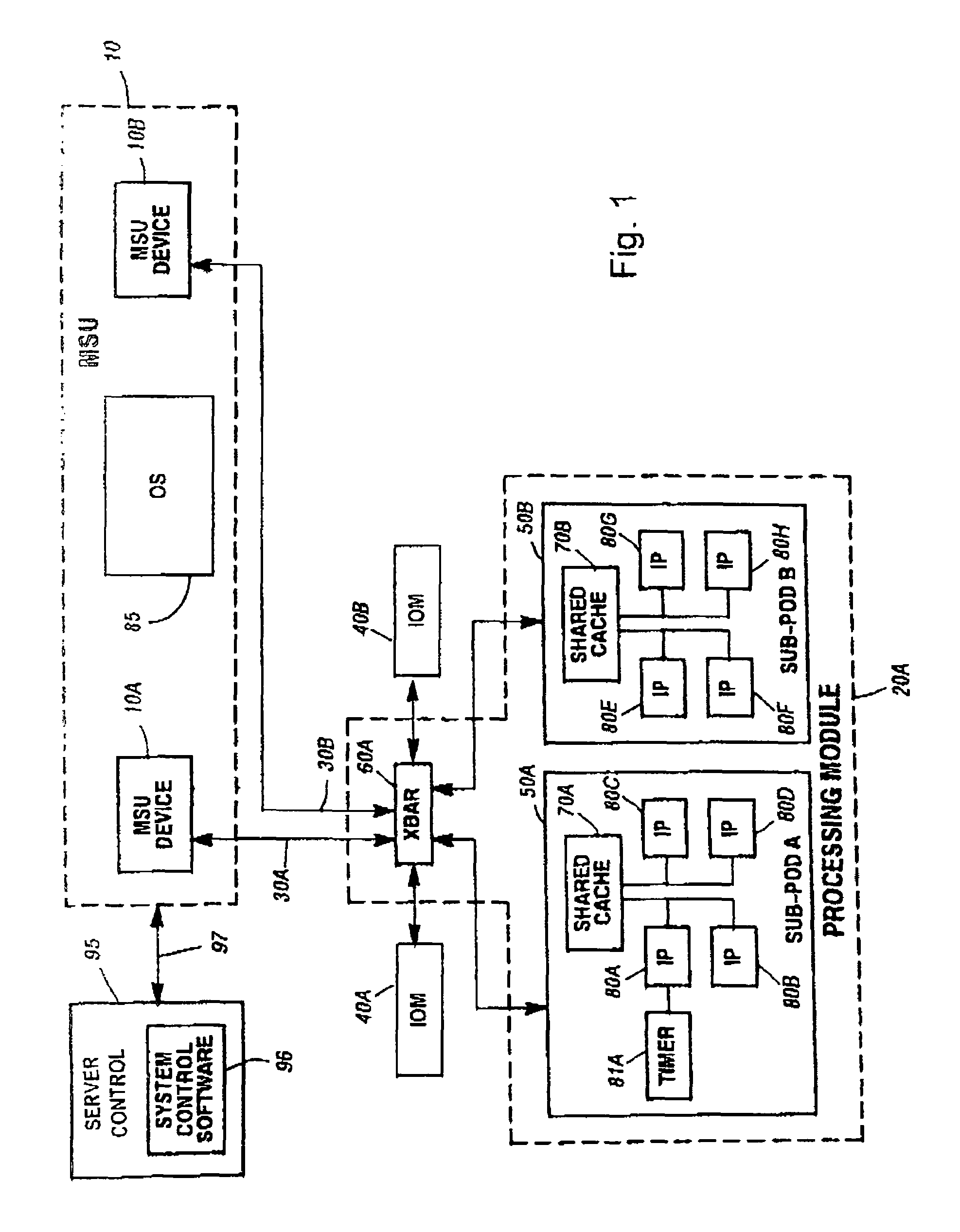
[0017]FIG. 1 is a block diagram of an exemplary computer system that may employ the current invention. This partitioned computer system includes a Memory Storage Unit (MSU) 10 which provides the main memory facility for the system The MSU includes one or more MSU devices individually shown as MSU 10A and MSU 10B, which each contains a predetermined portion of the memory space of the system There may be multiple MSU's in a partitioned computer system.

[0018]The system further includes a processing module (PODs) 20. A POD provides the processing capability for partitions within the computer system A greater number of PODs may be included in the system than are shown in FIG. 1. The POD is coupled to each of the MSU devices via a dedicated, point-to-point connection referred to as an MSU Interface (MI), individually shown as MIs 30A and 30B. For example, MI 30A interfaces POD 20 to MSU device 10A, and MI 30B interfaces POD 20 to MSU 10B device. The POD inc...


PUM


Abstract

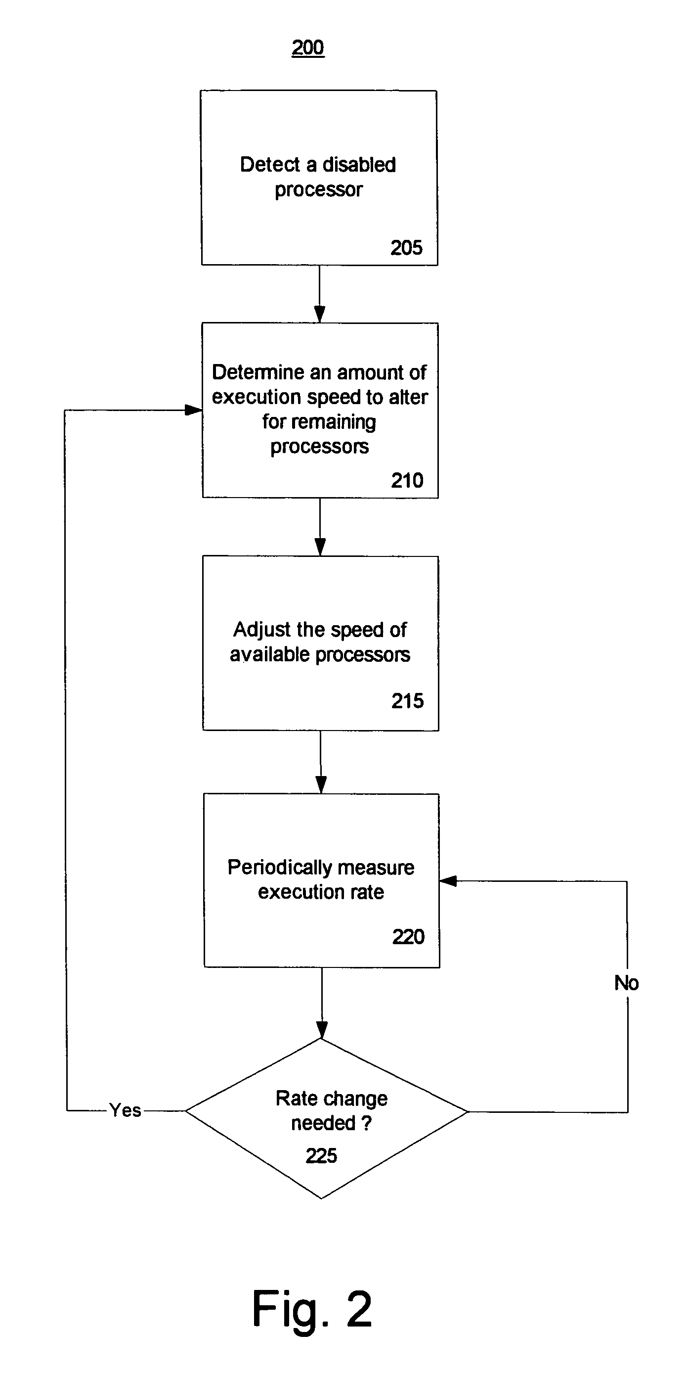
A method and system for maintaining the execution speed of a multiprocessor computer system includes automatically detecting a change in instruction execution rate in a disabled processor by a threshold amount and determining an amount of change in instruction execution rate to adjust an actual system-level instruction execution rate to approximate a target system-level instruction execution rate. The target system-level execution rate being pre-determined. Thereafter, the method adjusts one or more instruction processor execution rates such that the actual system-level instruction execution rate approximates the target system-level instruction execution rate to overcome the loss of the disabled processor. One embodiment of the invention involves the use of a processor key for licensing of processor resources within the computer system and offers the option of enabling a dynamic processor recovery method as well as an automatic execution rate regulation method.

Description

REFERENCE TO RELATED APPLICATIONS[0001]The following U.S. patent applications have material relevant to the current invention and are incorporated herein by reference in their entirety.[0002]U.S. application Ser. No. 09 / 676,162 filed Sep. 29, 2000, entitled “Authorization Key System for Selectively Controlling the Performance of a Data Processing System”.[0003]U.S. patent application Ser. No. 10 / 744,685 filed Dec. 23, 2003, entitled “System And Method For Metering The Performance Of A Data Processing System”.FIELD OF THE INVENTION[0004]The current invention relates generally to data processing systems, and more particularly to methods for maintaining a constant instruction execution rate within a computer system.BACKGROUND OF THE INVENTION[0005]Many businesses are intolerant to the loss of service in computer equipment that provides services to their business or customers. One example is telephone switchboard service. Businesses may use telephony equipment to route calls for their e...

Claims


Application Information

Patent Timeline
Patent Type & Authority Patents(United States)
IPC IPC(8): G06F11/00
CPCG06F11/2025G06F11/2046G06F11/2035G06F11/2028G06F11/2038
Inventor HOFFMAN, PHILLIP M.PARAGAS, JESSICA A.MATYOK, ANTHONY P.STELL, JEFFERY A.MAUER, SHARON M.THOMPSON, JAMES W.
Owner UNISYS CORP
Learn More