Lighting system for vehicle and vehicle incorporating same

a technology for vehicle lighting and vehicle body, which is applied in the direction of anti-theft devices, anti-theft cycle devices, cycle equipments, etc., can solve the problems of imposing assembly problems and high cost of large-capacity diodes, and achieve the effect of simplifying the system

Active Publication Date: 2010-06-01
HONDA MOTOR CO LTD
View PDF7 Cites 1 Cited by
  • Summary
  • Abstract
  • Description
  • Claims
  • Application Information

AI Technical Summary

Benefits of technology

[0017]In the present invention, according to the first aspect, the power supply circuit operates in response to the output from the alarm apparatus to the lighting control circuit. Accordingly, in an ignition off state of the ignition switch, by activating the lighting control circuit in response to the alarm apparatus output, the winker lamps can be caused to light up or flicker to produce alarm.
[0018]Since the lighting control circuit operates normally to control the winker lamps to light up or flicker in this manner, current is not supplied from the power supply such as a battery directly to all winker lamps. Accordingly, the system can be simplified because elimination of requirement of any no-return diodes of large current capacity which is used in order to cause a winker lamp to be selectively lit directly by a battery or the like upon alarming.
[0019]In the present invention, according to the second aspect, the lighting control circuit connected to the power supply such as a battery through the ignition switch is not biased in an ignition off state of the ignition switch. Therefore, in an ignition off state, the battery or the like is connected to the power supply circuit such that the power supply such as a battery can be connected to the lighting control circuit through the power supply circuit in response to a trigger of the alarm apparatus. Accordingly a large current capacity diode that are externally connected can be omitted since upon alarm indication, the winker lamps caused to light up or flicker similar to ordinary winker indication.
[0020]Further, according to the third aspect of the present invention, the winker lamps can be changed over between winker indication and hazard indication in accordance with an instruction outputted from the microcomputer in response to operation of the winker switch and the hazard switch. Consequently, a hazard holding relay is not required and thus it can be omitted from the system.

Problems solved by technology

Further, it is necessary to used four large capacity diodes D1, D2, D3 and D4, through which current from the battery flows, and such large capacity diodes may be expensive and may impose assembling problems.

Method used


Image

  • Lighting system for vehicle and vehicle incorporating same
  • Lighting system for vehicle and vehicle incorporating same
  • Lighting system for vehicle and vehicle incorporating same

Examples


first embodiment

[0039]Operation of the lighting system of the first embodiment is described below.

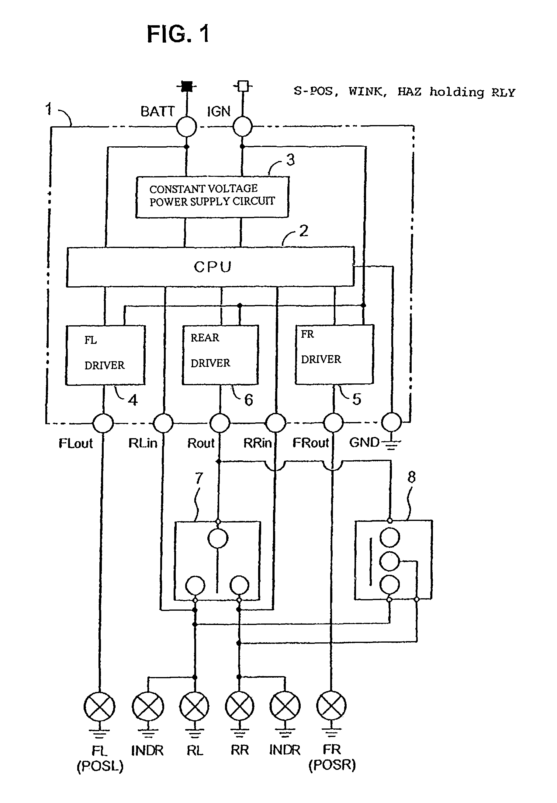
[0040]If the ignition switch is switched on, then the battery is connected to the relay unit 1 and the CPU 2 is activated. At this time, the CPU 2 supplies a lighting driving signal of a low duty ratio to the left front driver 4 and the right front driver 5 so that the lamps may be lit as position lamps. The CPU 2 supplies a lighting driving signal of a high duty ratio to the rear driver 6 so that the lamps are lit as winker lamps.

[0041]When the winker switch 7 and the hazard switch 8 are not set on, only the left front driver 4 and the right front driver 5 are turned on in response to the lighting driving signal of the low duty ratio so that the left front lamp FL and the right front lamp FR are lit as position lamps.

[0042]Then, if the winker switch 7 is operated to the left rear lamp RL side for winker indication upon turning to the left, then the source of the rear driver (FET) 6 is connected to the...

second embodiment

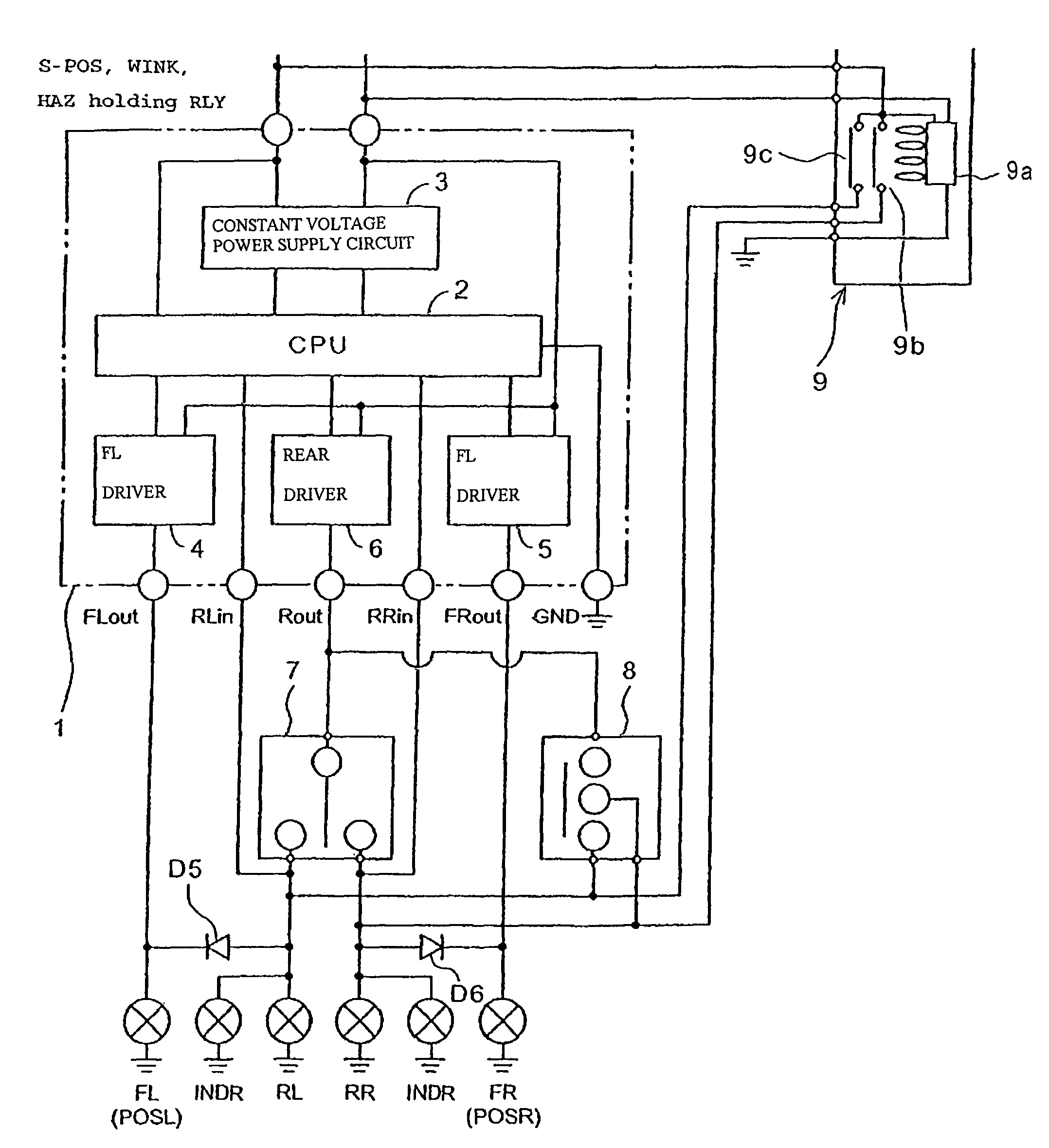
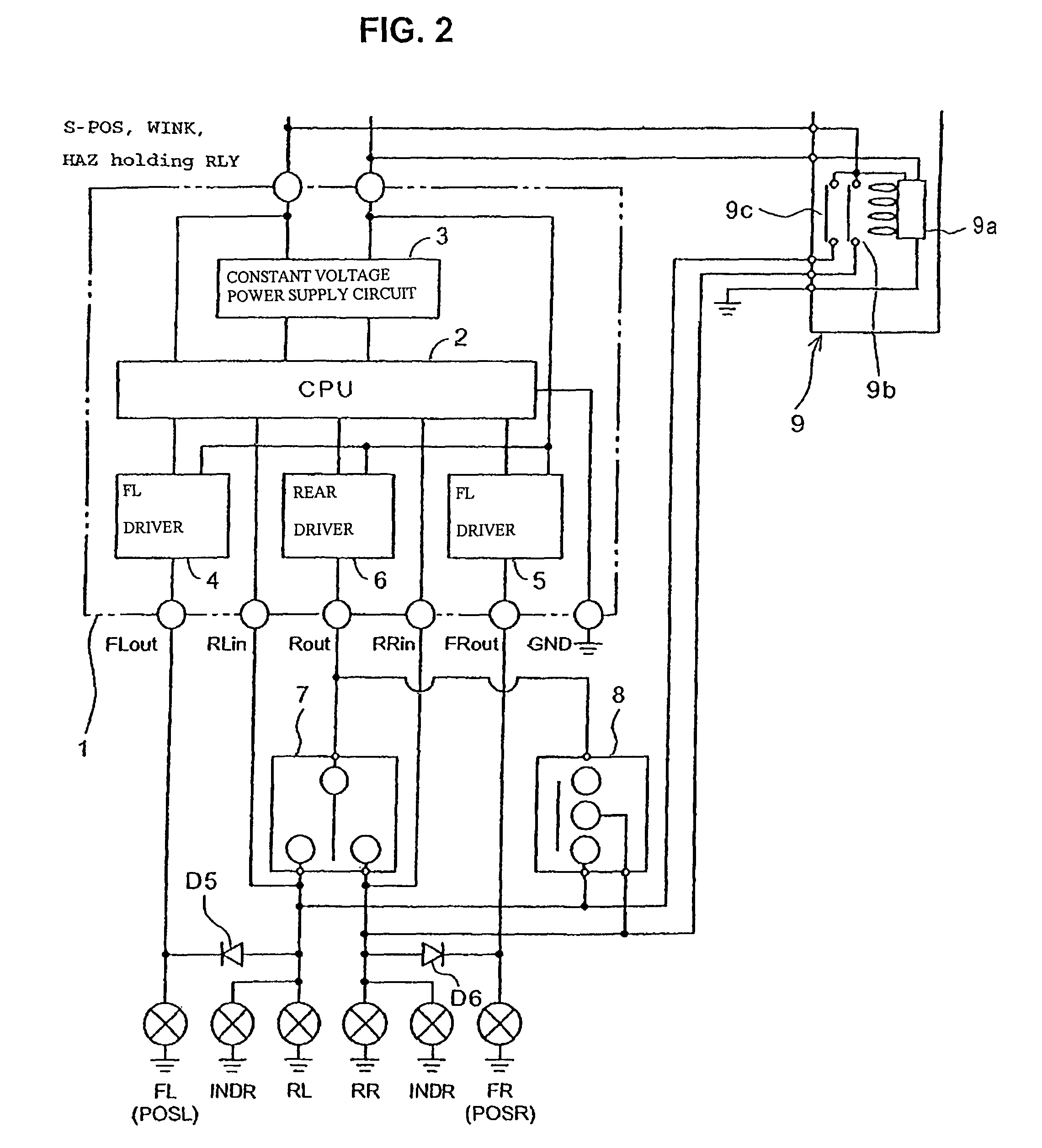
[0048]Now, a lighting system which is further used as an answerback for an antitheft apparatus 9, is described below. The answerback signifies that, when an antitheft apparatus operates, flickering operation same as operation of a hazard lamp is performed.

[0049]FIG. 2 is a system diagram of a lighting system according to the second embodiment which is ready for the answerback for the antitheft apparatus 9. An antitheft apparatus 9 is connected to the output side of a hazard switch 8, that is, the antitheft apparatus 9 is operatively connected to the left rear lamp RL and the right rear lamp RR, and to the hazard switch 8.

[0050]The antitheft apparatus 9 is a flasher relay which has a coil 9a and contacts 9b, 9c connected to an oscillation circuit. The coil 9a of the antitheft apparatus is excited in a predetermined period upon theft detection to turn the contacts 9b, 9c on and off. The antitheft apparatus 9 decides the theft parameter based on the inclination of the vehicle body whe...

fourth embodiment

[0064]Now, the present invention is described with reference to FIG. 4. The fourth embodiment includes a winker canceller 15. It may be note that details of a relay unit 12 (of FIG. 3) are omitted in the FIG. 4 for simplicity.

[0065]The winker canceller 15 includes a winker canceller control section 16, a steering angle sensor 17 for detecting the steering angle of the steering shaft of the vehicle (motorcycle), a set switch 18, and a cancel relay 19. The winker canceller control section 16 includes a vehicle speed input terminal VPLS for accepting a pulse signal of a period corresponding to the vehicle speed, a steering angle input terminal ANGL, a power supply voltage terminal Vcc, a set switch signal input terminal SET, a cancel signal output terminal CANCEL, a signal ground terminal SG and a power supply ground terminal PG.

[0066]The steering angle sensor 17 is connected to the steering angle input terminal ANGL, the power supply voltage terminal Vcc and the signal ground terminal...


PUM


Abstract

The lighting system having a plurality of winker lamps disposed on front and rear portions of a vehicle body, a winker switch, and a lighting control circuit which performs changeover function allowing the winker lamps at a front portion of the vehicle body to lit as position lamps. The lighting control circuit is connected to a battery through an ignition switch. The lighting system further includes a power supply circuit which supplies, in an ignition off state, power to the lighting control circuit in response to an output signal from an antitheft apparatus to cause the winker lamps to light up or flicker. The output terminal of the antitheft device is connected to an electrical connection formed between the winker switch and the left and right rear lamps.

Description

CROSS-REFERENCE TO RELATED APPLICATIONS[0001]The present application claims priority under 35 USC §119 based on Japanese patent application No. 2006-349487, filed on Dec. 26, 2006. The entire subject matter of this priority document is herein incorporated by reference.BACKGROUND OF THE INVENTION[0002]1. Field of the Invention[0003]The present invention relates to a lighting system for a vehicle, such as a motorcycle. More particularly, the present invention relates to a vehicle lighting system having reduced number of parts and simplified structure including application of a single filament bulb as a winker lamp and a position lamp.[0004]2. Description of the Background Art[0005]There are known lighting systems for vehicles, such as motorcycles, in which a single filament bulb is sometimes used as both of a winker lamp and a position lamp. In these systems, when the single filament bulb is operated as a winker lamp, current is supplied at a duty ratio of 100% to the single filament ...

Claims


Application Information

Patent Timeline
Patent Type & Authority Patents(United States)
IPC IPC(8): B60R25/10B60Q1/34B60Q1/38B62H5/20B62J6/00B62J6/16B62J99/00
CPCB60Q1/28B60Q1/38B60Q1/40B62J6/005B62J6/003B60R25/104B60R2325/306B62J6/015B62J6/056
Inventor TAKEUCHI, YOSHIAKIKONDO, TETSUYAKITAMURA, RYOHEI
Owner HONDA MOTOR CO LTD
Why Eureka
Try Eureka