System for measuring deflection of rotating shaft in wireless manner

Active Publication Date: 2010-05-20
KOREA PLANT SERVICE & ENG CO LTD
View PDF7 Cites 13 Cited by
  • Summary
  • Abstract
  • Description
  • Claims
  • Application Information

AI Technical Summary

Benefits of technology

[0014]Accordingly, the present invention has been made keeping in mind the above problems occurring in the prior art, and an object of the present invention is to provide a system for measuring the deflection of a rotating shaft in a wireless manner, in which angle division and measurement are performed in a non-contact manner, so that the run-out and offset of a rotating shaft are measured without the occurrence of slippage or error at the time of angle division, thereby enabling highly reliable measurement.
[0015]Another object of the present invention is to provide a system for measuring the deflection of a rotating shaft in a wireless manner, in which measured values are transmitted and processed in a wireless manner, so that the system can be simplified, has high mobility, and can be installed in a short time thanks to the easiness of the installation thereof.
[0017]Still another object of the present invention is to provide a system for measuring the deflection of a rotating shaft in a wireless manner, which enables a reduction in the exposure of a worker to radiation when the system is used for the alignment of the rotation shaft of a nuclear power plant.

Problems solved by technology

Although a contact-type division device has been adopted and used to measurer the run-out and offset of a rotating shaft, this method has a defect in that slippage occurs during angle division, and thus accurate angle division is not achieved, with the result that error occurs.
Meanwhile, a prior measurement method using non-contact-type displacement sensors has a defect in that great error occurs depending on the material of a measurement target object and an environment.
Furthermore, prior art angle division using a wired method and a prior art system for measuring run-out and offset have problems in that many work hours are required due to the setting work of installing sensors and data transmission lines, the range of application to parts is narrow, and the reliability of measurement cannot be achieved because noise is included in a transmitted signal value due to the long distance transmission of measured data using a plurality of transmission lines.
In particular, they have a problem in that it is almost impossible to apply them to narrow areas and complicated structures.
However, the system for measuring the strain of a flywheel rotor has a problem in that the strain sensor 4 is of a contact type, so that slippage occurs at the time of angle division, with the result that accurate angle division cannot be performed, thereby causing the frequent occurrence of error.

Method used


Image

  • System for measuring deflection of rotating shaft in wireless manner
  • System for measuring deflection of rotating shaft in wireless manner
  • System for measuring deflection of rotating shaft in wireless manner

Examples


Embodiment Construction

[0033]Reference now should be made to the drawings, in which the same reference numerals are used throughout the different drawings to designate the same or similar components.

[0034]A system for wirelessly measuring the deflection of a rotating shaft in a wireless manner according to the present invention will be described in detail below with reference to the accompanying drawings and preferred embodiments.

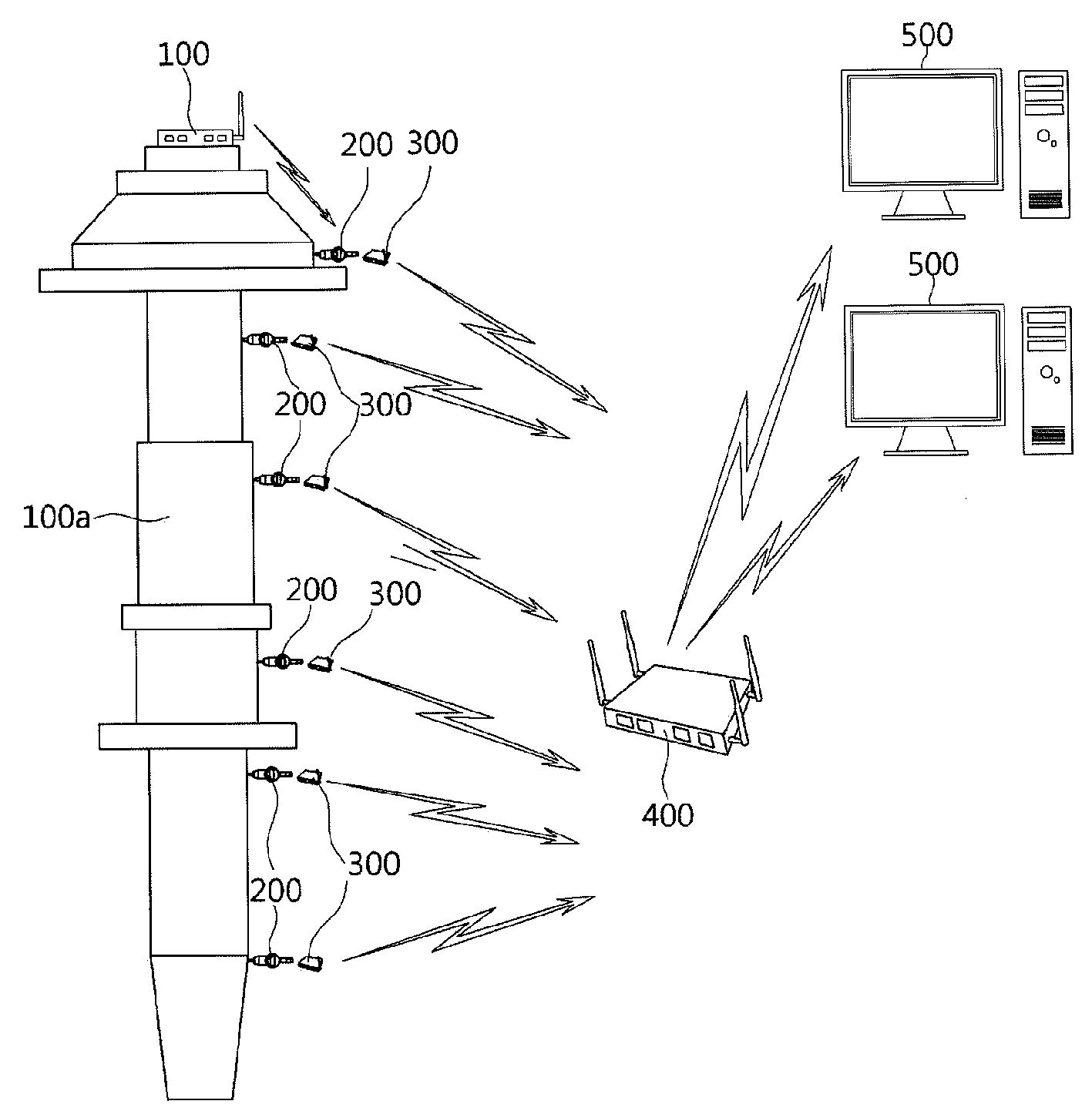
[0035]FIG. 8 is a conceptual diagram showing a system for measuring the deflection of a rotating shaft in a wireless manner according to the present invention, FIG. 9 is a block diagram showing a non-contact-type angle division device according to the present invention, FIG. 10 is a block diagram showing a wireless contact-type displacement sensor according to the present invention, FIG. 11 is a block diagram showing a relay according to the present invention, FIG. 12 is a block diagram showing signal transmission means according to the present invention, and FIG. 13 is a diagram...


PUM


Abstract

Disclosed herein is a system for measuring the deflection of a rotating shaft in a wireless manner. The system includes a non-contact-type angle division device, a plurality of wireless contact-type displacement sensors, a plurality of wireless transmitters, a relay, and a data reader. The non-contact-type angle division device is placed on a vertical rotating shaft and measures and transmits the angle of rotation of the rotating shaft. The wireless contact-type displacement sensors are installed on the outer circumferential surface of the rotating shaft, and measure the strain of the rotating shaft. The wireless transmitters transmit data about the displacement of the rotating shaft measured by the wireless contact-type displacement sensor. The relay receives and relays transmission signals from the non-contact-type angle division device and the wireless transmitters. The data reader receives the transmission signals from the relay, and performs simulation reading.

Description

BACKGROUND OF THE INVENTION[0001]1. Field of the Invention[0002]The present invention relates generally to a system for measuring the deflection of the rotating shaft of a rotating object, and, more particularly, to a system for measuring the deflection of a rotating shaft in a wireless manner, in which data about the deflection of the rotating shaft of the rotating object, particularly data about run-out and offset, measured through non-contact-type angle division using a wireless method is transmitted to a collection system and is then read, so that the installation and handling of the system can be facilitated and the run-out and offset of a large-size rotating shaft can be accurately and easily measured.[0003]2. Description of the Related Art[0004]In general, rotating objects require that run-out and offset are measured to inspect the extent of the wear of the cuter circumferential surface of a rotating shaft and the true roundness of the rotating shaft.[0005]In particular, in o...

Claims


Application Information

Patent Timeline
IPC IPC(8): G01M13/00
CPCH04Q2209/43H04Q9/00G01B7/00G01B7/30G01B7/16
Inventor KIM, NAG-JEAMCHOI, SANG-HOONKIM, SEONG-BONGPARK, GYOO-SUP
Owner KOREA PLANT SERVICE & ENG CO LTD
Why Eureka
Try Eureka