
Fast lock circuit for a phase lock loop

a phase lock and fast lock technology, applied in the field of electronic devices, can solve the problems of increased lock time, current shunted to ground, waste of energy,

Inactive Publication Date: 2010-06-01
MONTEREY RES LLC
View PDF87 Cites 34 Cited by
  • Summary
  • Abstract
  • Description
  • Claims
  • Application Information

AI Technical Summary

Benefits of technology

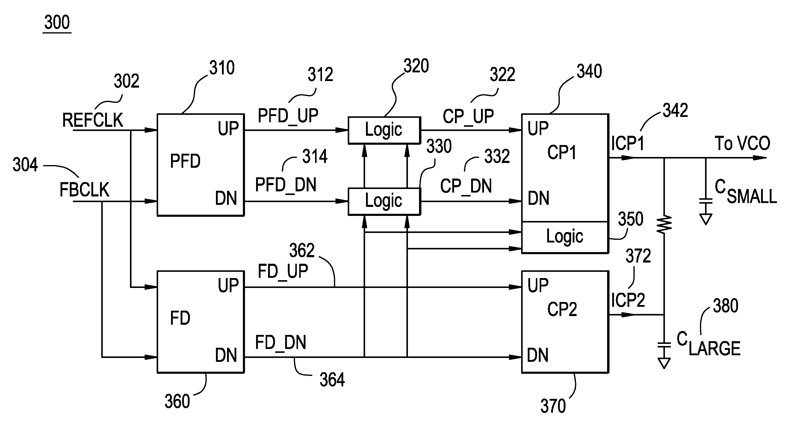
[0008]One embodiment of the present invention utilizes a logic circuit coupled to the phase frequency detector, frequency detector and two charge pumps. The logic circuit outputs signals from the phase frequency detector circuit when the PLL is locked. The logic circuit outputs signals from the frequency detector circuit before the PLL has achieved lock. As a result, a constant current is supplied to a large loop filter capacitor before the PLL has achieved lock. Therefore, using the novel logic circuit to supply constant current charges the large loop filter capacitor continuously and avoids a slow down in charging the large loop filter capacitor. Accordingly, current is no longer wasted and the lock time of the circuit is improved.
[0012]According to one embodiment, the lock circuit further includes a second logic circuit coupled to the first charge pump for increasing the amount of the first current output before the phase locked loop achieves lock.

Problems solved by technology

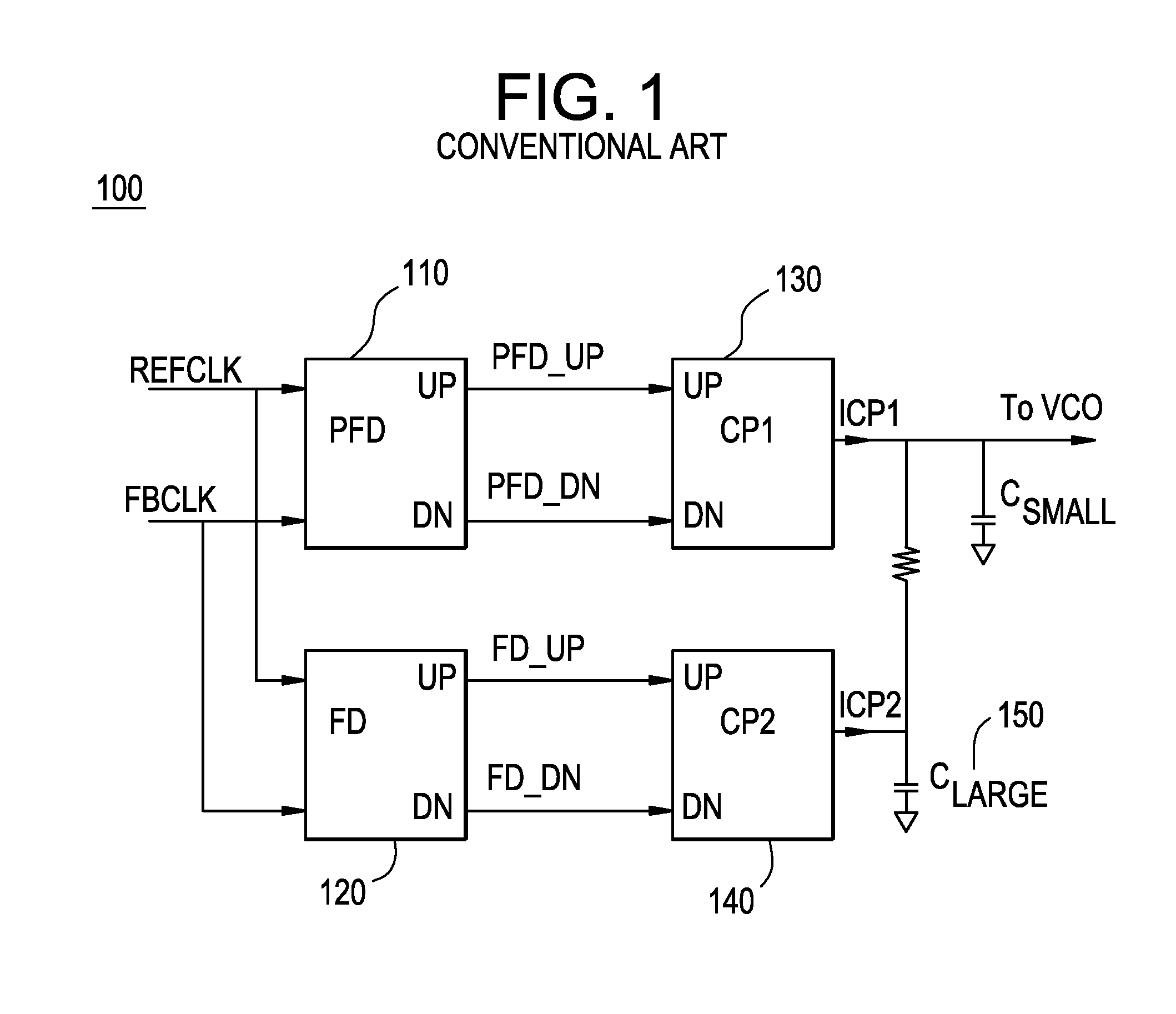
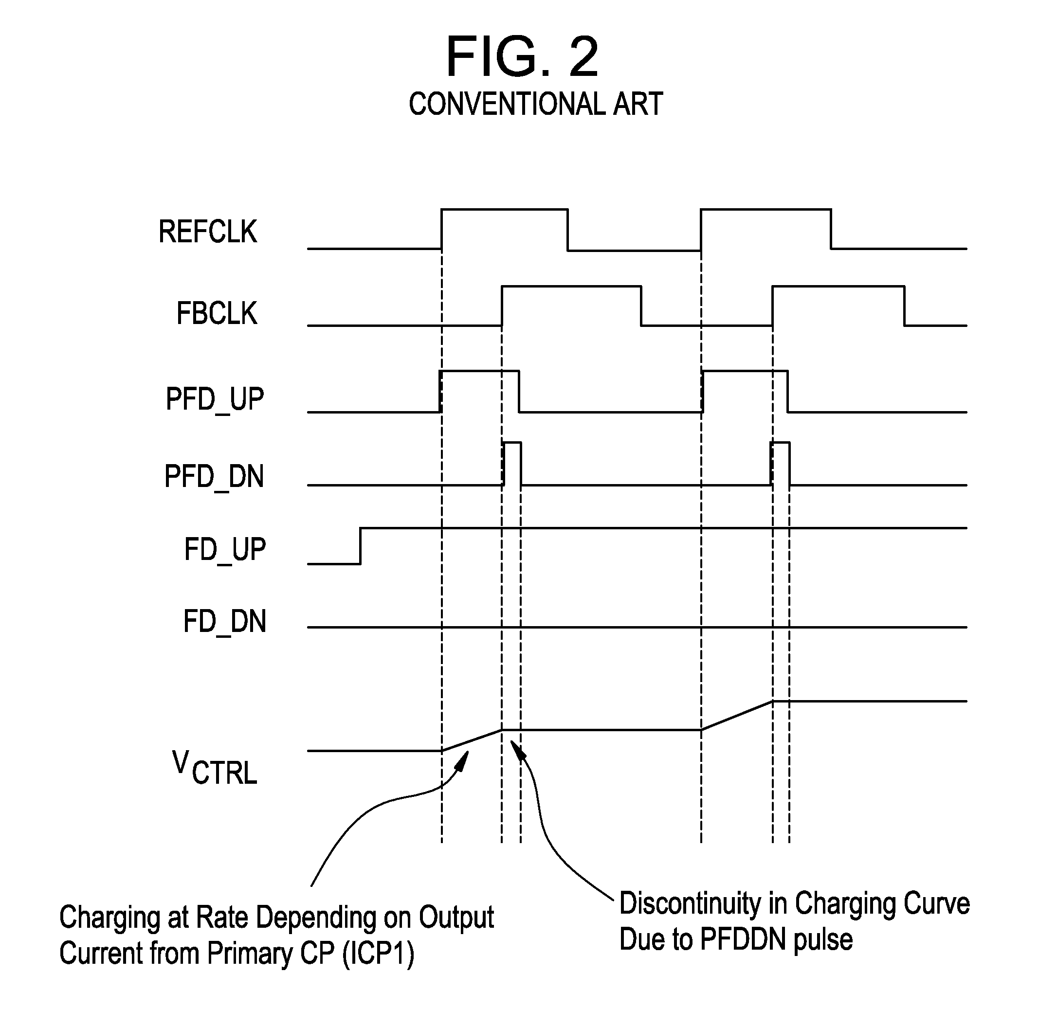
As a result, during the time that the current is not steered onto the loop filter, the current is shunted to ground and wasted because it is no longer used to charge the loop filter.
As a result, the lock time increases.

Method used


Image

  • Fast lock circuit for a phase lock loop
  • Fast lock circuit for a phase lock loop
  • Fast lock circuit for a phase lock loop

Examples


Embodiment Construction

[0022]Reference will now be made in detail to embodiments of the present invention, examples of which are illustrated in the accompanying drawings. While the invention will be described in conjunction with these embodiments, it will be understood that they are not intended to limit the invention to these embodiments. On the contrary, the invention is intended to cover alternatives, modifications and equivalents, which may be included within the spirit and scope of the invention as defined by the appended claims. Furthermore, in the following detailed description of the present invention, numerous specific details are set forth in order to provide a thorough understanding of the present invention. However, it will be evident to one of ordinary skill in the art that the present invention may be practiced without these specific details. In other instances, well known methods, procedures, components, and circuits have not been described in detail as not to unnecessarily obscure aspects ...


PUM


Abstract

A fast lock circuit for phase lock loop comprising a frequency detector, a phase frequency detector, a logic unit and a corresponding charge pump for the frequency and the phase frequency detectors. Embodiments of the present invention use the logic unit to relay signals from the phase frequency detector circuit to the charge pump when the PLL is in lock. The logic circuit relay signals from the frequency detector circuit before the PLL is in lock. As a result, a constant current is supplied to a large loop filter capacitor before lock. In one embodiment, additional logic circuit may be used to maximize the output current. Therefore, using the logic circuit to supply constant current charges the large loop filter capacitor continuously and avoids a slow down in charging the large loop filter. Accordingly, current is no longer wasted and the lock time is improved.

Description

RELATED APPLICATIONS[0001]This application claims the benefit and priority to a provisional application Ser. No. 60 / 787,862, inventors Kennedy et al., entitled “A FAST LOCK CIRCUIT FOR A PHASE LOCK LOOP” that was filed on Mar. 31, 2006. The above-cited provisional application is incorporated herein in its entirety.TECHNICAL FIELD[0002]Embodiments of the present invention relate to the field of electronics. More particularly, embodiments of the present invention relate to a fast lock circuit for a phase lock loop.BACKGROUND ART[0003]A phase-locked loop (PLL) is a closed-loop feedback control system that maintains a generated signal in a fixed phase relationship to a reference signal. More importantly, the PLL is used widely in radio, telecommunications, computers and other electronic applications where it is desired to stabilize a generated signal or to detect signals in the presence of noise. For example, the PLL is widely used for synchronization purposes, in communication for cohe...

Claims


Application Information

Patent Timeline
IPC IPC(8): H03L7/087H03L7/093H03L7/095
CPCH03L7/087H03L7/113H03L7/0898H03L7/095Y10S331/02
Inventor KENNEDY, IANO'SULLIVAN, EUGENELOMBAARD, CAREL J.
Owner MONTEREY RES LLC
Learn More