
Silicon crystallization apparatus and silicon crystallization method thereof

a silicon crystallization and crystallization method technology, applied in the direction of soldering apparatus, instruments, auxillary welding devices, etc., can solve the problems of poor heat resistance of glass substrates, poor device characteristics, and inability to uniformize the crystal particles formed in the second region

Inactive Publication Date: 2010-06-01
LG DISPLAY CO LTD
View PDF12 Cites 9 Cited by
  • Summary
  • Abstract
  • Description
  • Claims
  • Application Information

AI Technical Summary

Benefits of technology

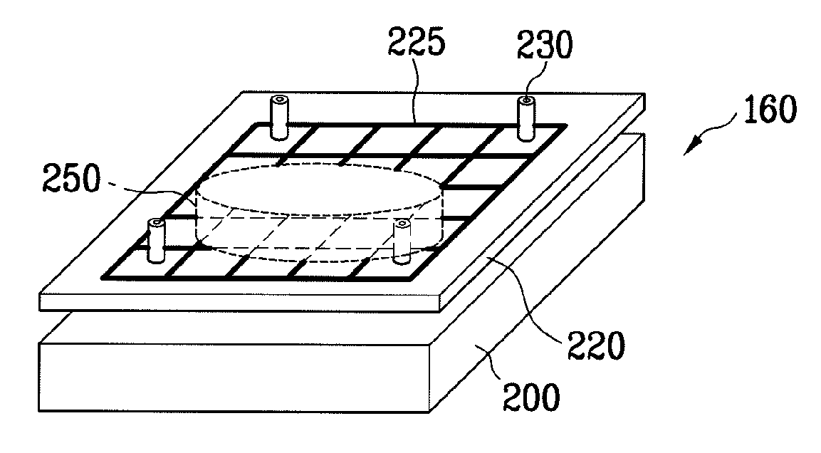
[0047]An object of the invention is to provide a silicon crystallization apparatus and a silicon crystallization method thereof, in which it is possible to form an alignment key without additional photolithography, and to adjust the substrate to a correct position by sensing the deviation of the substrate when the substrate is loaded.

Problems solved by technology

Glass substrates have poor heat-resistance, and hence expensive quartz substrates having excellent heat-resistance should be used.
When fabricating a polysilicon thin film by using the high temperature fabrication process, inadequate crystallization may occur due to high surface roughness and fine crystal grains, thereby resulting in poor device characteristics, as compared to polysilicon formed by the low temperature fabrication process.
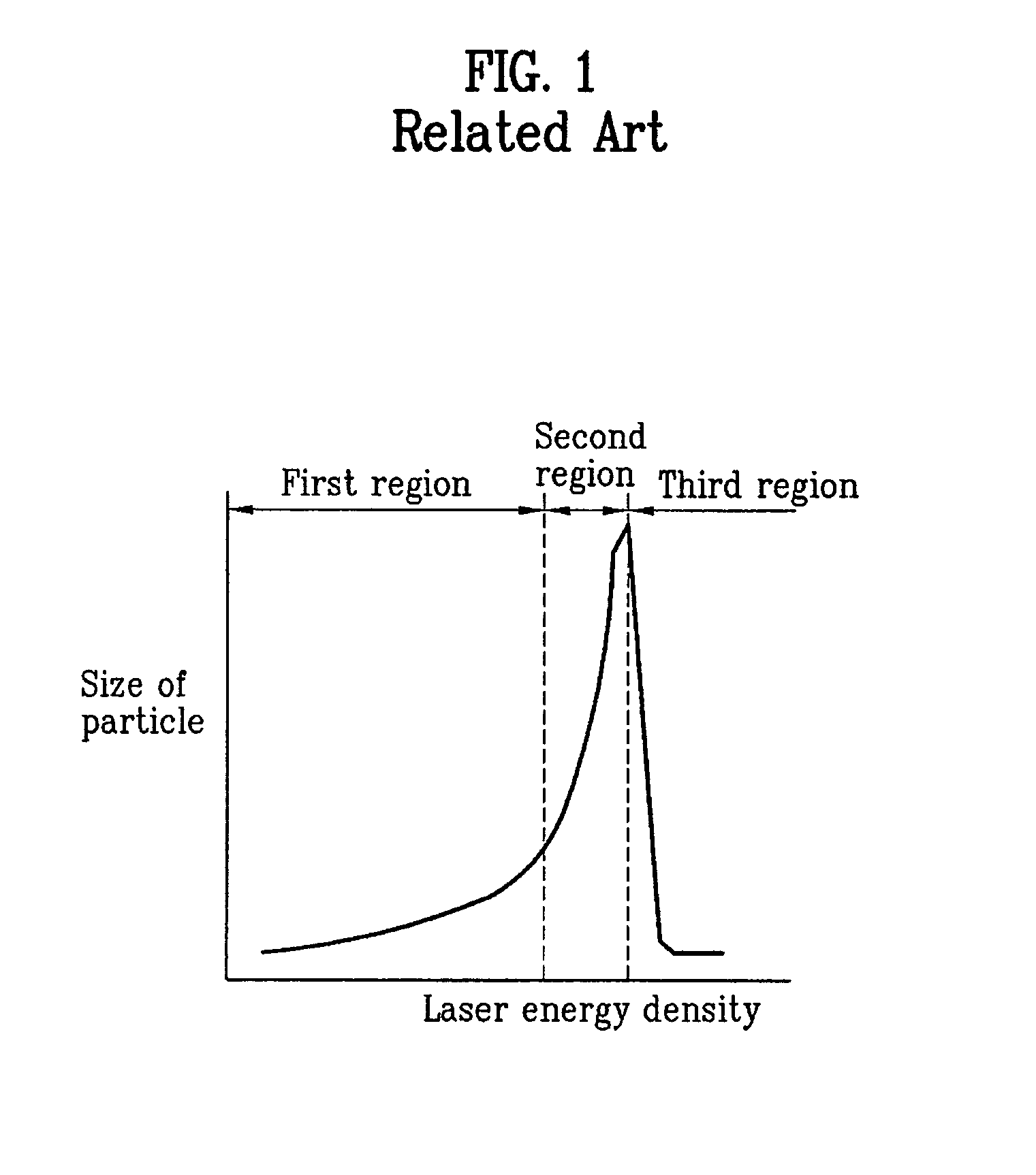
However, the crystal particles formed in the second region are not uniform.
However, the interfaces between the many polysilicon crystal particles act as impediments to electric current flow, thereby decreasing the reliability of the thin film transistor device.
In addition, collisions between electrons may occur within the many crystal particles to cause damage to the insulating layer due to the collision current and deterioration, thereby resulting in product degradation or defects.
As a result, it is difficult to control the position of laser beam overlapped portions.
Accordingly, if the laser beam overlapped portions correspond to the pixel regions or a channel region, it may cause deleterious low picture quality and low operation speed.
For this, there arises a requirement to perform photolithography to form the additional alignment key, thereby placing a burden on the silicon crystallization process.

Method used


Image

  • Silicon crystallization apparatus and silicon crystallization method thereof
  • Silicon crystallization apparatus and silicon crystallization method thereof
  • Silicon crystallization apparatus and silicon crystallization method thereof

Examples


Embodiment Construction

[0081]Reference will now be made in detail to the preferred embodiments of the invention, examples of which are illustrated in the accompanying drawings. Wherever possible, the same reference numbers will be used throughout the drawings to refer to the same or like parts.

[0082]Hereinafter, a silicon crystallization apparatus and a silicon crystallization method according to the invention will be described with reference to the accompanying drawings.

[0083]FIG. 6 illustrates a plane view of respective regions formed on a substrate according to the invention. FIG. 6 shows a substrate 100 for a thin film transistor array of an LCD device is defined as a display area 110 for displaying a substantial image, and a non-display area 120 surrounds the display area 110. An amorphous silicon layer is deposited over the entire surface of the substrate 100.

[0084]On the display area 110, multiple gate and data lines (not shown, positioned in portions except pixel regions of the display area) cross...


PUM

PropertyMeasurementUnit
temperatureaaaaaaaaaa
wavelengthaaaaaaaaaa

Abstract

A novel silicon crystallization apparatus and a silicon crystallization method renders it is possible to form alignment key without additional photolithography, and to adjust a substrate to a correct position by sensing a deviation of the substrate when the substrate is loaded. The silicon crystallization apparatus includes a moving stage being moved in a horizontal direction, and a fixing plate provided in the moving stage, to fix a substrate. A rotating frame is provided in the moving stage, to rotate the fixing plate.

Description

CROSS-REFERENCE TO RELATED APPLICATIONS[0001]This non-provisional application claims the benefit under 35 U.S.C. §119 of Korean Application No. P2003-096578, filed on Dec. 24, 2003, which is hereby incorporated by reference as if fully set forth herein.BACKGROUND OF THE INVENTION[0002]1. Field of the Invention[0003]The invention relates to a silicon crystallization method and a silicon crystallization apparatus, in which it is possible to form an alignment key without additional photolithography, and to adjust the substrate to a correct the position by sensing a deviation of the substrate when the substrate is loaded.[0004]2. Discussion of the Related Art[0005]Various displays increase in demand as information technologies develop. Recently, many efforts have been made to research and develop various flat display panels such as a liquid crystal display device (LCD), a plasma display panel (PDP), an electroluminescent display (ELD), a vacuum fluorescent display (VFD), and the like. S...

Claims


Application Information

Patent Timeline
Patent Type & Authority Patents(United States)
IPC IPC(8): B23K26/02B23K26/00B23K26/06B23K26/08B23K37/04C30B11/00C30B29/06G02F1/35H01L21/00H01L21/20H01L21/324H01L21/477H01L21/68
CPCB23K26/063B23K26/0823B23K26/0853H01L21/68C30B11/005C30B29/06H01L21/2026B23K37/0461B23K26/0622H01L21/02532H01L21/0268
Inventor JUNG, YUN HOKIM, YOUNG JOO
Owner LG DISPLAY CO LTD
Learn More