
Mine counter measure system

a measure system and land mine technology, applied in the direction of mine sweeping, offensive equipment, transportation and packaging, etc., can solve the problems of adding explosive danger to personnel who then enter the land mine field, the method is not very effective or efficient, and the threat of land mines is severe to military and civilian personnel

Active Publication Date: 2010-06-01
RAYTHEON CO
View PDF157 Cites 6 Cited by
  • Summary
  • Abstract
  • Description
  • Claims
  • Application Information

AI Technical Summary

Benefits of technology

[0007]It is a further object of this invention to provide such a system which is highly effective and which can be used during armed conflict.
[0008]It is a further object of this invention to provide such a system which is efficient.
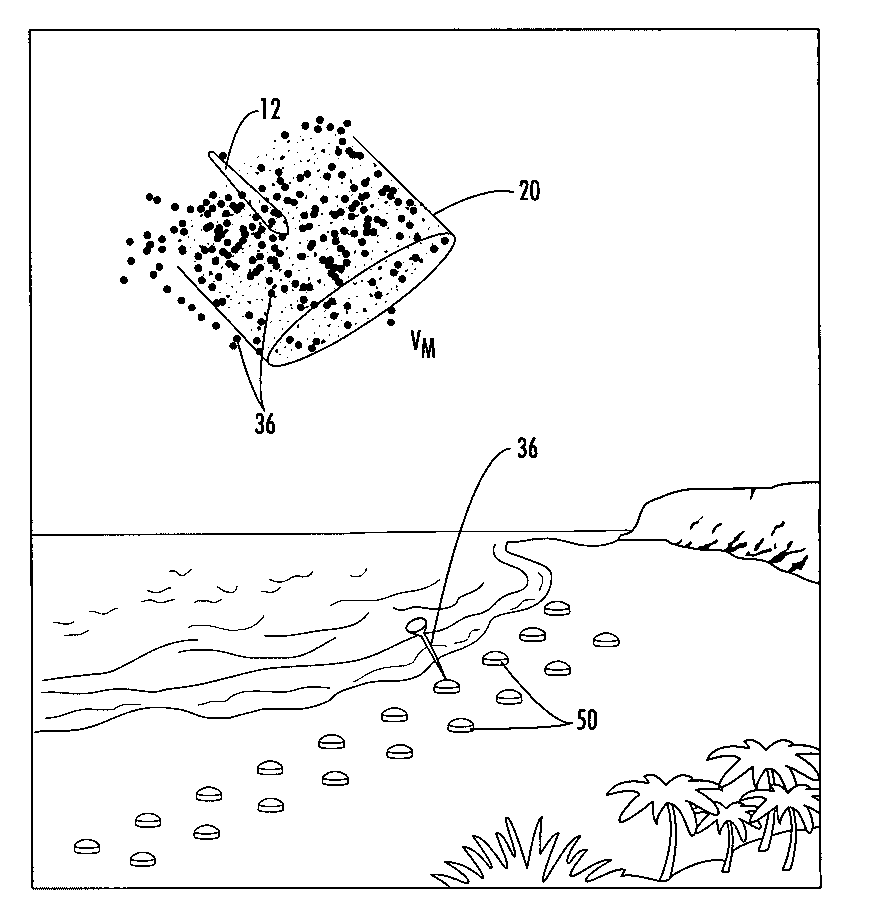
[0010]It is a further object of this invention to provide such a system which can efficiently and effectively detonate land mines buried in the sand and also under the water.
[0013]In one example, each rod has a length to diameter ratio of greater than 5 and preferably a length to diameter ratio greater than or equal to 10. In one embodiment, the stabilizer is a plurality of fins on the distal end of each rod. In another embodiment, the stabilizer is a flared distal end of the rod. Typically, the proximal end of each rod is pointed. In one example, the proximal end of each rod includes a poly-wedge shape to decrease the drag on the rod. Also, it is preferred that the center of gravity of each rod is proximate the distal end of the rod to orient the proximal end of the rod downward.
[0016]In one example, the housing is a shell. In another example, the housing is a payload. Further included may be a missile for deploying a plurality of said payloads. Typically, the rods are staggered in the housing for better packaging efficiency.
[0018]One mine counter measure system in accordance with this invention features a plurality of munition housings each including, an explosive, and a plurality of kinetic energy rods about the explosive, each rod having a stabilizer for aligning the rod about its velocity vector to better penetrate the surface above a mine and each rod including a poly-wedge shaped tip to decrease the drag on the rod and a length to diameter ratio of greater than or equal to 10. A carrier deploys the munition housings over a minefield.

Problems solved by technology

Land mines pose a severe threat to military and civilian personnel.
The idea of detonating land mines using conventional weapons and ordnances is known but such methods are not very effective or efficient since many ordnances would be required to detonate the numerous possible land mines in a given area.
But, never is there a guarantee that all the land mines would be detonated and, worse, some shape charges could fail to detonate resulting in an added explosive danger to personnel who then enter onto the land mine field.
Also, this approach would not be used during a war where troops are required to engage the enemy from the beach.
Conventional approaches fail to effectively counter such tactics during wartime.

Method used


Image

  • Mine counter measure system
  • Mine counter measure system
  • Mine counter measure system

Examples


Embodiment Construction

[0035]Aside from the preferred embodiment or embodiments disclosed below, this invention is capable of other embodiments and of being practiced or being carried out in various ways. Thus, it is to be understood that the invention is not limited in its application to the details of construction and the arrangements of components set forth in the following description or illustrated in the drawings.

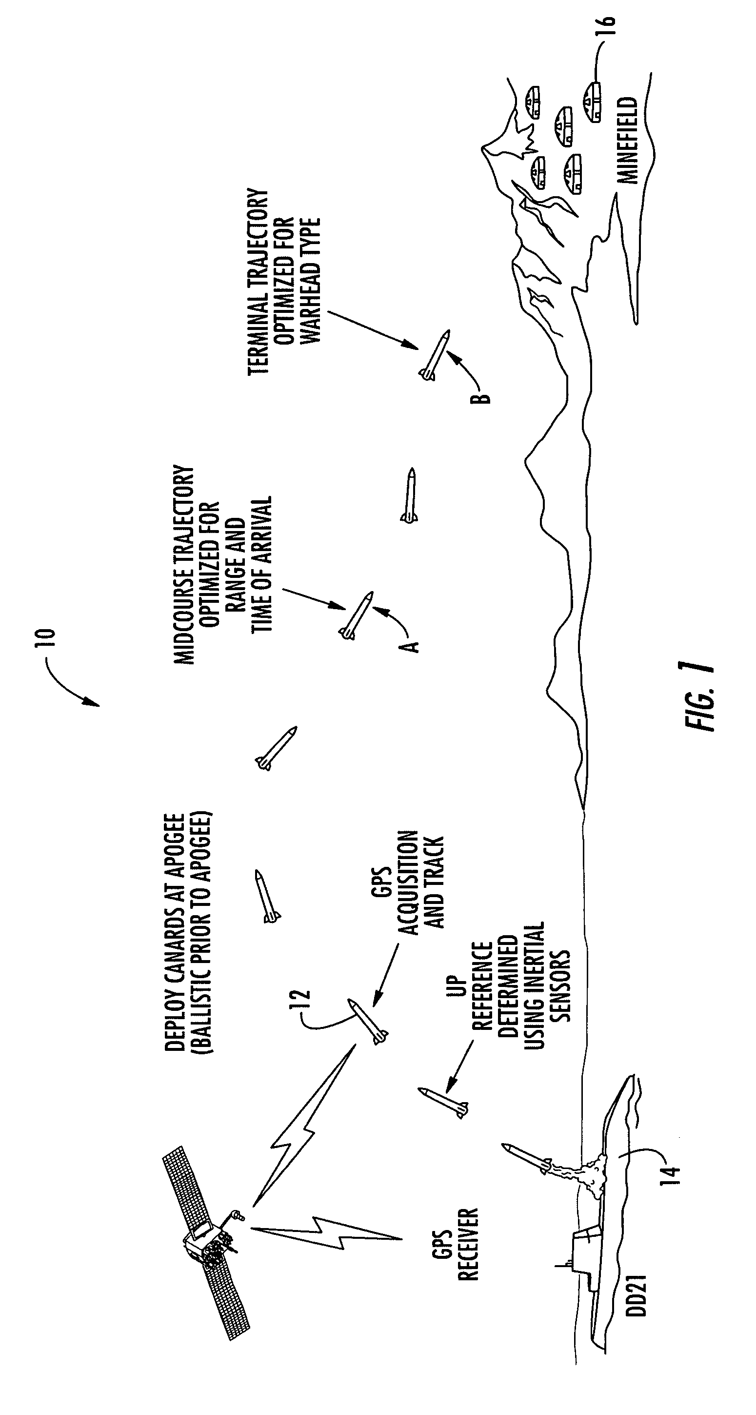
[0036]Mine counter measure system 10, FIG. 1 includes, in one example, missile 12 deployed from ship or submarine 14 or other launcher. In this specific example, missile 12 is an XM 982 Excalibur 155 mm long range guided missile with GPS tracking capability and having a trajectory optimized for range and time of arrival at position A and then having a trajectory optimized for rod delivery at position B over minefield 16. Other ordnances and delivery mechanisms, however, are within the scope of this invention.

[0037]As shown in FIG. 2, missile 12 includes bays 18 housing deployable munitions,...


PUM


Abstract

A method of destroying mines in a minefield buried under the surface includes deploying a munition including a plurality of kinetic energy rods each having a stabilizer into a position above the minefield and deploying the rods above the minefield to fall towards the minefield each aligned along a velocity vector to penetrate the surface and destroy the mines.

Description

RELATED APPLICATIONS AND PRIORITY CLAIM[0001]This application is a divisional application of prior U.S. patent application Ser. No. 10 / 685,242 filed on Oct. 14, 2003 now abandoned which is incorporated into this application by reference, and to which this application claims priority.FIELD OF THE INVENTION[0002]This invention relates to a land mine counter measure system.BACKGROUND OF THE INVENTION[0003]Land mines pose a severe threat to military and civilian personnel. The idea of detonating land mines using conventional weapons and ordnances is known but such methods are not very effective or efficient since many ordnances would be required to detonate the numerous possible land mines in a given area.[0004]One current idea is to deploy a net carrying shape charges onto the land mine field. But, never is there a guarantee that all the land mines would be detonated and, worse, some shape charges could fail to detonate resulting in an added explosive danger to personnel who then enter...

Claims


Application Information

Patent Timeline
Patent Type & Authority Patents(United States)
IPC IPC(8): B63G7/02F41H11/12F42B12/06F42B12/20F42B12/62F42B12/64
CPCF41H11/12F42B12/64F42B12/60F42B12/202
Inventor LLOYD, RICHARD M.
Owner RAYTHEON CO
Learn More