Catalytic combustor
a combustor and catalytic technology, applied in the field of catalytic combustor, can solve the problems of reducing combustion performance, affecting the reaction efficiency of catalysts, and affecting the moisture in the passage through the bypass flow passage, and achieve the effect of reducing the amount of unburned hydrogen discharged
- Summary
- Abstract
- Description
- Claims
- Application Information
AI Technical Summary
Benefits of technology
Problems solved by technology
Method used
Image

Examples
first embodiment
of the Catalytic Combustor
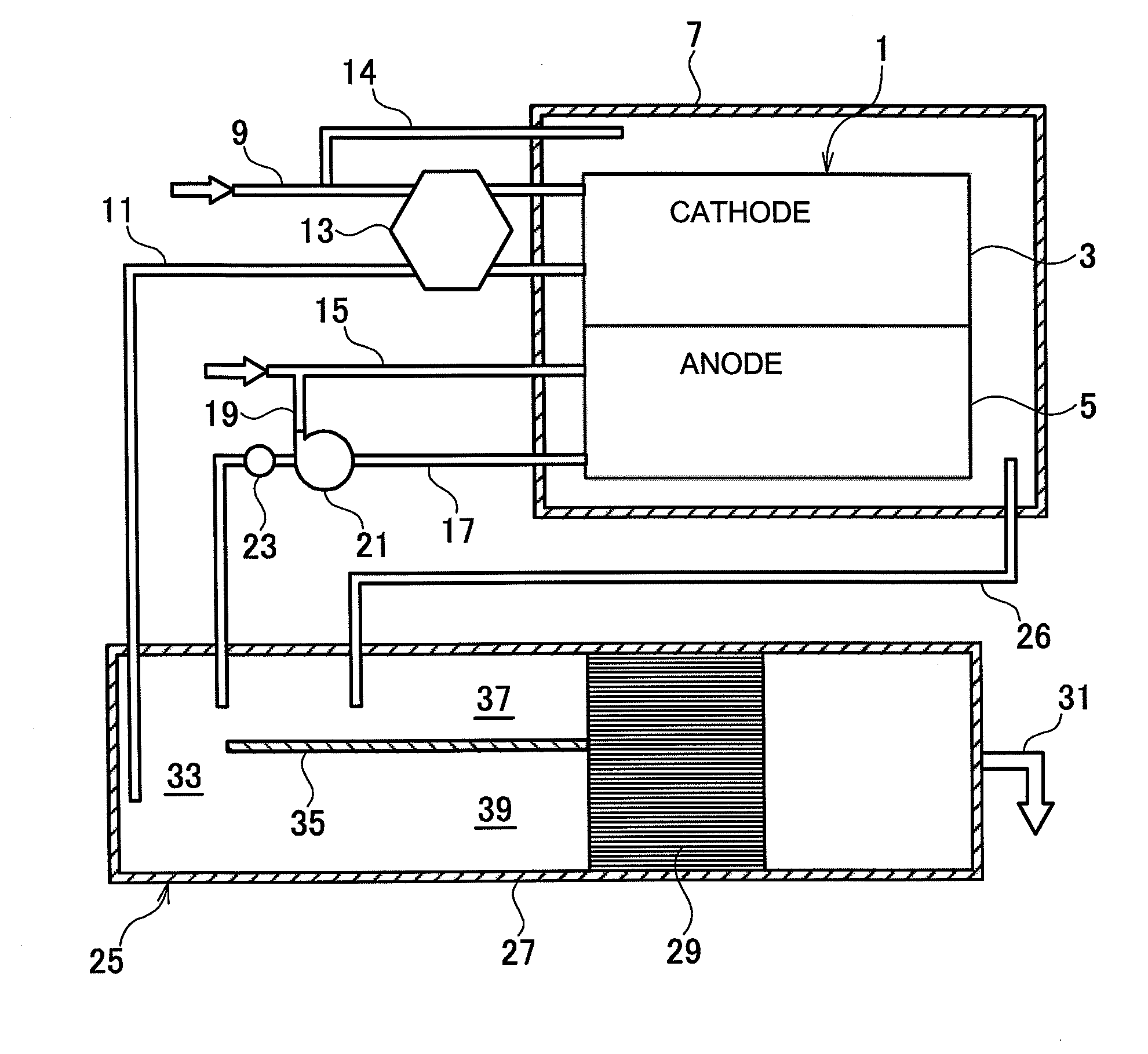
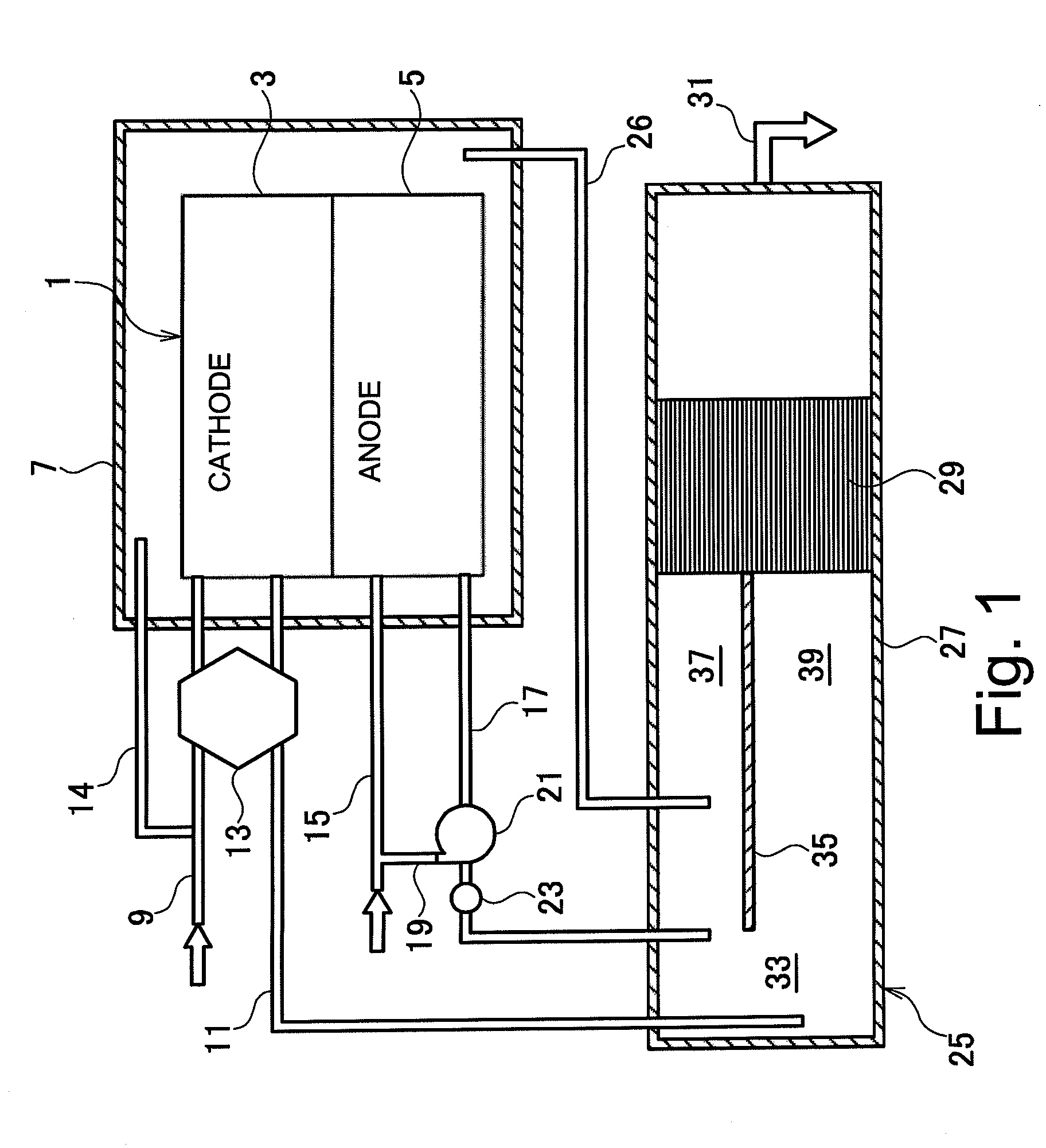
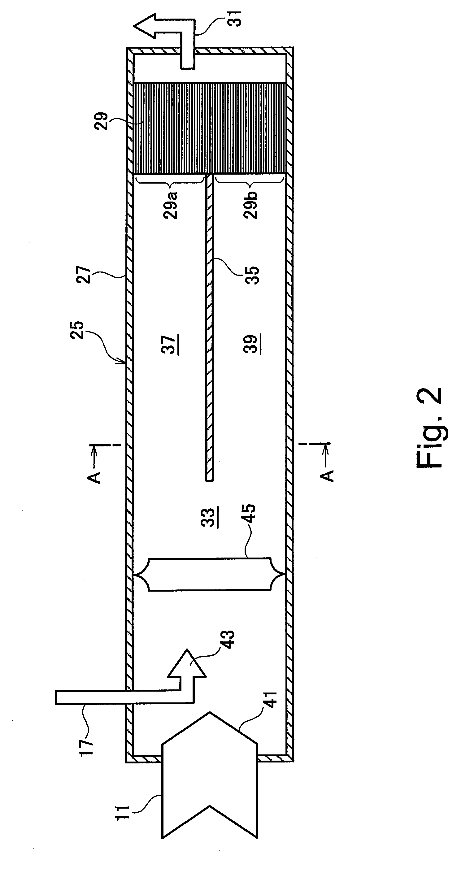
[0043]Referring now to FIGS. 2, 3(a) and 3(b), the main features of the catalytic combustor 25 will now be described in detail. Basically, the catalytic combustor 25 of this embodiment of the present invention mixes anode off gas discharged from the anode 5 of a fuel cell 1 with cathode off gas discharged from the cathode 3 of the fuel cell 1 and then combusts the mixture of gases.
[0044]FIG. 2 is a simplified longitudinal cross sectional view of the catalytic combustor 25 to be used in the fuel cell system shown in FIG. 1 in accordance with the first embodiment of the present invention. FIG. 3(a) is a simplified transverse cross sectional view of the catalytic combustor 25 illustrated in FIG. 2 taken along section line A-A of FIG. 2. FIG. 3(b) is a simplified transverse cross sectional view, similar to FIG. 3(a), of the catalytic combustor 25, but in accordance with a first variation of the first embodiment of the present invention.
[0045]The housing 27 of t...
second embodiment
of the Catalytic Combustor
[0058]FIG. 4 is a side cross sectional view of a second embodiment of the catalytic combustor 25. FIG. 5(a) is a cross sectional view taken along section line B-B of FIG. 4. Component parts of the second embodiment of the catalytic combustor 25 that are the same as the parts of the first embodiment are indicated with the same reference numerals as in the first embodiment and explanations thereof are omitted for the sake of brevity.
[0059]In the embodiment, as shown in FIG. 5(b), a partitioning pipe 47 is used as the partition wall that divides the gas flow passage 33 into a plurality of flow paths. The partitioning pipe 47 has a smaller diameter than the housing 27. The partitioning pipe 47 encloses an upper portion of the inside of the housing 27 to divide the gas flow passage 33 inside the housing 27 into two vertically arranged flow paths, namely, the upper flow path 37 and the lower flow path 39.
[0060]The partitioning pipe 47 is arranged such that the do...
third embodiment
of the Catalytic Combustor
[0076]FIG. 6 is a side cross sectional view of a third embodiment of the catalytic combustor 25. Component parts of the third embodiment of the catalytic combustor 25 that are the same as the parts of the second embodiment are indicated with the same reference numerals as in the second embodiment and explanations thereof are omitted for the sake of brevity.
[0077]This embodiment is the same as the catalytic combustor 25 of the second embodiment shown in FIG. 4, except that the ventilation air discharge pipe 26 shown in FIG. 1 is connected to the upper flow path 37 and the temperature sensor 51 is omitted.
[0078]The ventilation air discharge pipe 26 is arranged to pass through the housing 27 and protrude into the upper flow path 37 at a position upstream of the anode off gas pipe 17. A ventilation air introducing port 53 is arranged on the tip of the ventilation air discharge pipe 26 in such a fashion as to face downstream.
[0079]Thus, small amounts of hydrogen...
PUM
| Property | Measurement | Unit |
|---|---|---|
| volumetric density | aaaaa | aaaaa |
| volumetric density | aaaaa | aaaaa |
| volumetric density | aaaaa | aaaaa |
Abstract
Description
Claims
Application Information
 - R&D
- Intellectual Property
- Life Sciences
- Materials
- Tech Scout
- Unparalleled Data Quality
- Higher Quality Content
- 60% Fewer Hallucinations
Browse by: Latest US Patents, China's latest patents, Technical Efficacy Thesaurus, Application Domain, Technology Topic, Popular Technical Reports.
© 2025 PatSnap. All rights reserved.Legal|Privacy policy|Modern Slavery Act Transparency Statement|Sitemap|About US| Contact US: help@patsnap.com