
Antenna device for injecting or extracting microwaves into/from tubular hollow bodies, and device for measuring mass flow by using antenna devices of this type

an antenna device and tubular hollow body technology, which is applied in waveguide devices, liquid/fluent solid measurement, instruments, etc., to achieve the effects of low loss, high efficiency and increased efficiency in propagation direction

Inactive Publication Date: 2010-05-11
SCHENCK PROCESS GMBH
View PDF15 Cites 22 Cited by
  • Summary
  • Abstract
  • Description
  • Claims
  • Application Information

AI Technical Summary

Benefits of technology

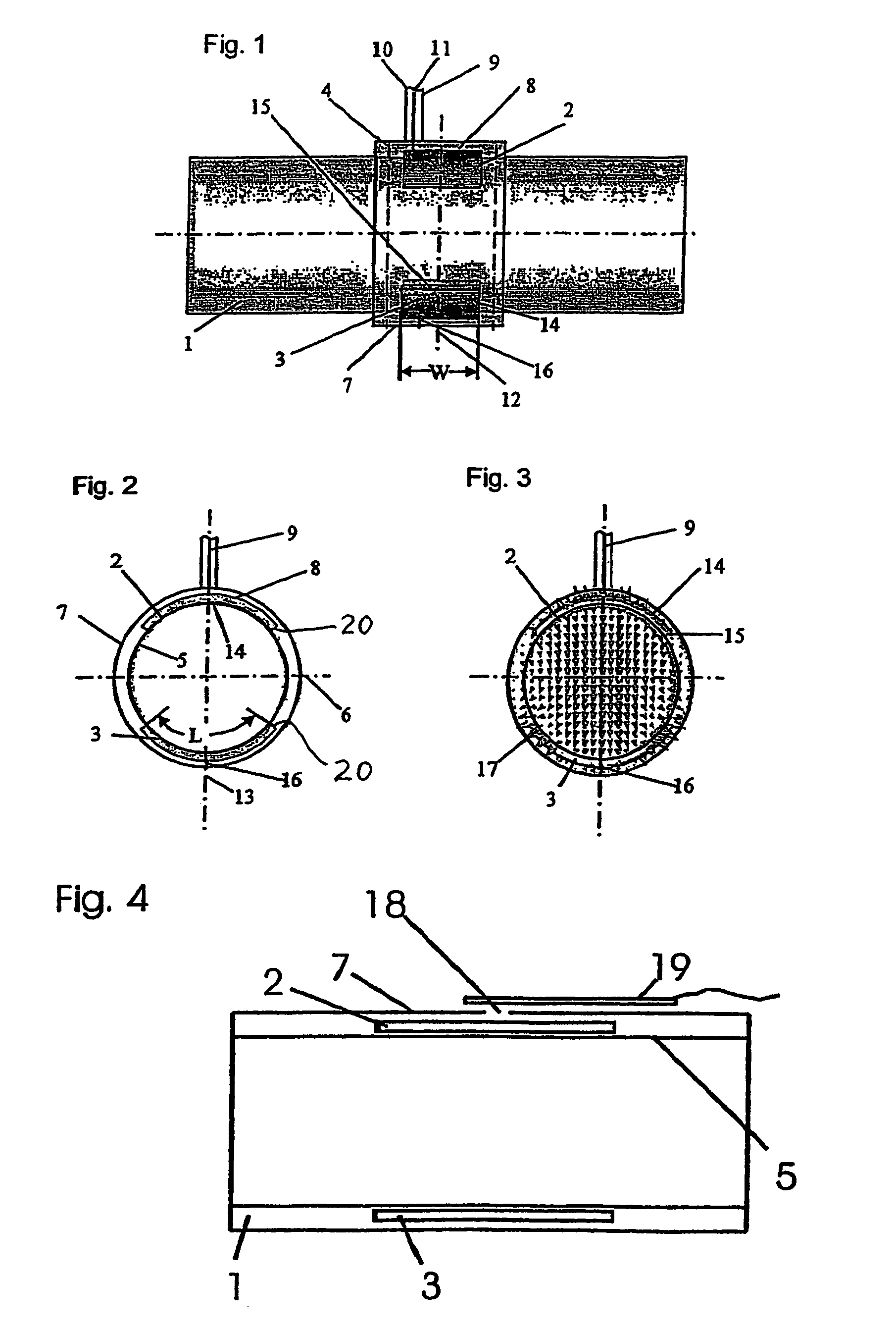
[0012]The invention has the advantage, that an integration in the hollow body arises due to the insertion or setting-in of patch element pairs into the inner pipe wall, whereby the inner cross-section of the through-flowable pipe remains unchanged. Thereby, simultaneously, the evolution of turbulences during the through-flowing of multi-phase powder-form or fluid media is prevented, of which the unhindered throughflow is often necessary for the following or subsequent processes. In that regard, especially the integration of two oppositely arranged bent or curved patch elements has been shown to be advantageous, because therewith a uniform spreading-out or propagation over the entire cross-section area with spreadable or propagable (propagatable) microwaves as electromagnetic waves is possible, through which the dielectric fluctuations due do multi-phase particle streams or flows are exactly detectable. With such an integrated antenna arrangement, however, also other longer high frequency transmissions are possible with a high efficiency in open pipe-shaped hollow conductors or waveguides, which are only slightly hampered by interference, especially due to an oriented in-coupling. Through the use of such integrated patch elements in the inner pipe wall, a microwave in-feeding supply or also an out-coupling can be carried out, for example through a coaxial conductor connector in a simple manner, through which relatively low losses arise, especially in connection with an oriented in-coupling.
[0013]In a particular embodiment of the invention it is provided that the in-feeding or supply of the microwave energy is provided off-center to the patch element width, which has the advantage that thereby an axially oriented wave spreading or propagation takes place in the pipe-shaped hollow body, whereby the efficiency in the propagation direction increases and simultaneously the interferences by a reflected wave propagation during the out-coupling are reduced. Thereby, not only can the measurement accuracy for a particle distribution or a mass flow determination be improved, but also thereby the transmission quality of the microwave propagation in open hollow conductor or waveguide structures can be increased. Namely particularly, also for pure transmission purposes, thereby an efficiency of far over 50% can be achieved between the in-coupling and out-coupling locations. Therefore, advantageously with relatively low in-coupling energies, relatively long microwave transmission sections or paths, or high measurement accuracies for prescribed measurement sections or paths, can be achieved.

Problems solved by technology

With such an integrated antenna arrangement, however, also other longer high frequency transmissions are possible with a high efficiency in open pipe-shaped hollow conductors or waveguides, which are only slightly hampered by interference, especially due to an oriented in-coupling.

Method used


Image

  • Antenna device for injecting or extracting microwaves into/from tubular hollow bodies, and device for measuring mass flow by using antenna devices of this type
  • Antenna device for injecting or extracting microwaves into/from tubular hollow bodies, and device for measuring mass flow by using antenna devices of this type
  • Antenna device for injecting or extracting microwaves into/from tubular hollow bodies, and device for measuring mass flow by using antenna devices of this type

Examples


Embodiment Construction

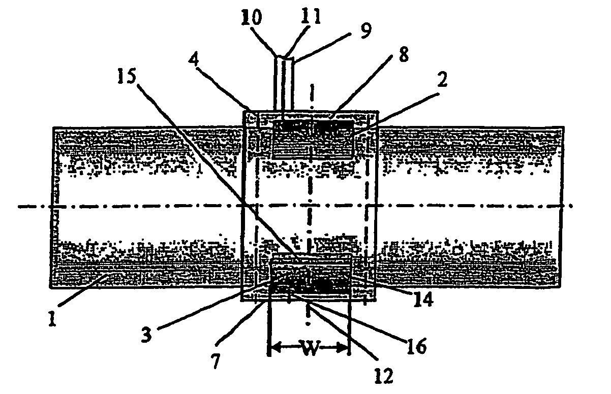
[0021]In FIG. 1 of the drawing, there is illustrated an antenna arrangement for high frequency in-feeding or out-coupling in a pipe-shaped hollow body 1 as a hollow conductor or waveguide, which antenna arrangement consists of so-called patch elements 2, 3, which are integrated in the inner wall 5 of the pipe-shaped hollow body 1.

[0022]The pipe-shaped hollow body 1 represents the cut-out section of a simple round pipe, as it is used for the pneumatic conveying of coal dust in the cement industry, that preferably consists of metal. However, the hollow body 1 can also represent a hollow conductor or waveguide that is not specified or suitable for conveying, as it is used, for example, for the transmission of high frequency waves in the microwave technology.

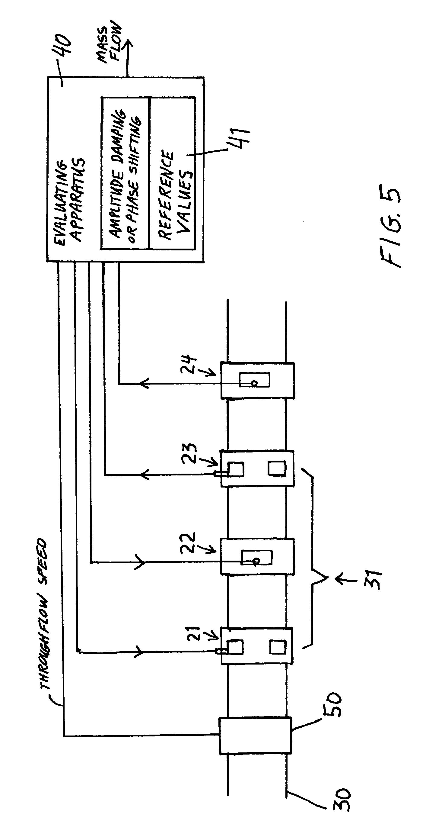
[0023]In the present example embodiment it is provided, quantitatively to determine the coal dust particles flowing through the hollow body 1 embodied as a conveyor pipe, by means of two antenna arrangements (see FIG. 5). With such ...


PUM


Abstract

An antenna arrangement for coupling high frequency electromagnetic waves into or out of a pipe-shaped hollow body includes two patch antenna elements that are located opposite one another and integrated in the pipe inner wall (5) of the hollow body (1), and have curved surfaces fitted to the curved longitudinal pipe inner wall of the hollow body (1). An apparatus for mass flow measurement includes at least two of such antenna arrangements axially spaced apart from one another in a conveyor pipe section.

Description

FIELD OF THE INVENTION[0001]The invention relates to an antenna arrangement for coupling microwaves into or out of a pipe-shaped hollow body, and to an apparatus for mass flow measurement in pipe-shaped hollow bodies by means of such antenna arrangements.BACKGROUND INFORMATION[0002]For the transmission of high frequency energy through the atmosphere or in hollow bodies, antenna arrangements are known, which radiate electromagnetic high frequency waves in these media, whereby the high frequency waves also can again be received via such antenna arrangements. Such antenna arrangements serve for the conversion of electrical signals into electromagnetic waves or electromagnetic waves into electrical signals. These arrangements are used for information transmission or for evaluating the transmission space. Especially in the measurement technology, often spacing distances, speeds or the distribution of solid bodies or particles in dielectric media are detected through use of high frequency...

Claims


Application Information

Patent Timeline
Patent Type & Authority Patents(United States)
IPC IPC(8): G01P5/08G01F1/7088
CPCG01F1/662G01F1/7088H01Q1/38G01F1/86H01P5/107G01F1/74
Inventor ALLENBERG, BERNDPENIRSCHKE, ANDREASJAKOBY, ROLF
Owner SCHENCK PROCESS GMBH
Learn More