
Method for refinery foulant deposit characterization

Inactive Publication Date: 2010-05-04
EXXON RES & ENG CO
View PDF5 Cites 3 Cited by
  • Summary
  • Abstract
  • Description
  • Claims
  • Application Information

AI Technical Summary

Problems solved by technology

The lack of this common thread of data sharing has been an impediment to experience sharing in the past.

Method used


Image

  • Method for refinery foulant deposit characterization
  • Method for refinery foulant deposit characterization
  • Method for refinery foulant deposit characterization

Examples


example 1

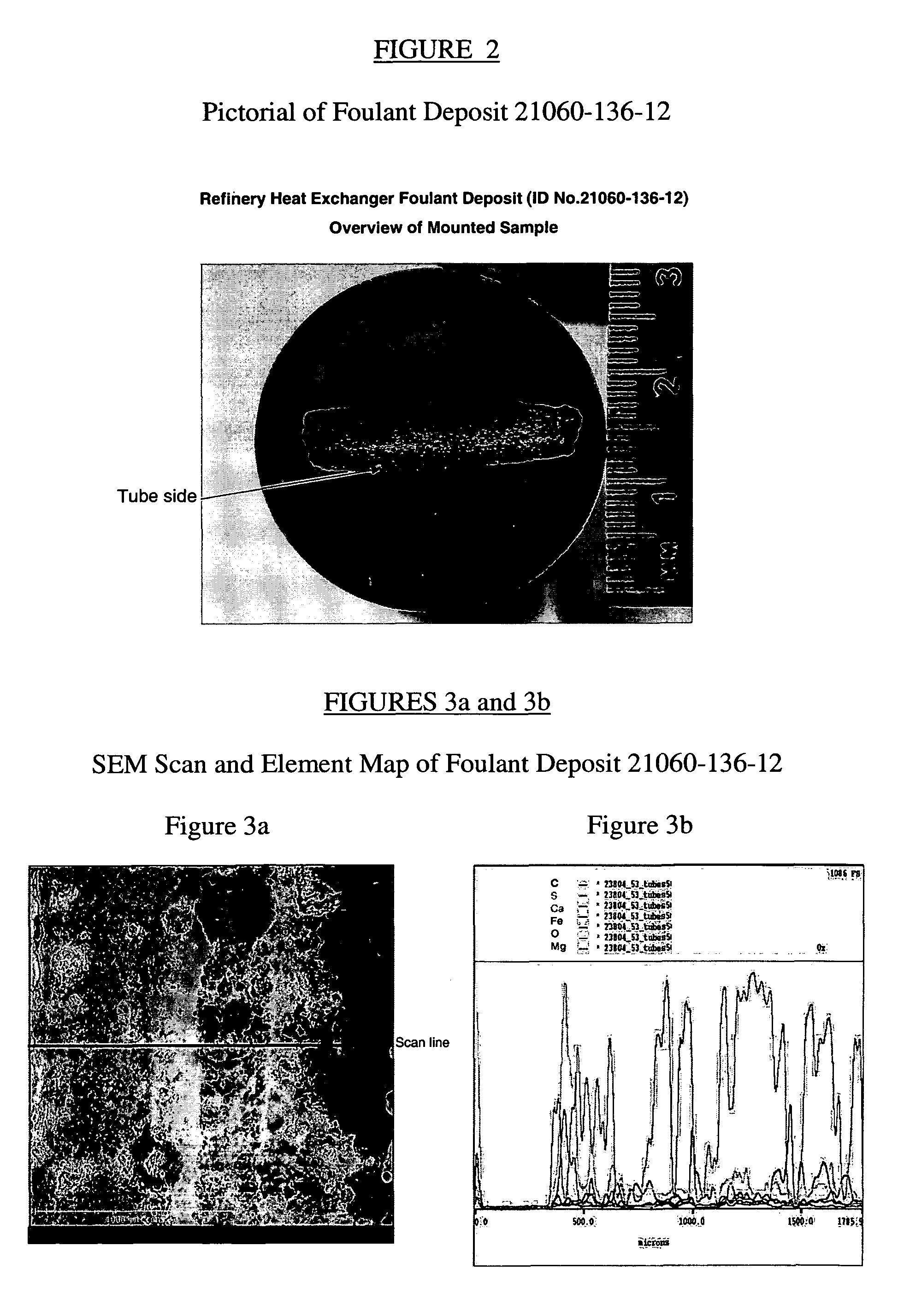
[0059]The method of the present invention was applied to a fouling deposit from a fouled refinery pre-heat train exchanger. FIG. 2 shows a pictorial of the fouling deposit. FIGS. 3a and 3b show an SEM scan and the element map of the deposit. FIG. 4 shows the major elements to quantify from the SEM / EDX scan. Table 2 gives the analytical results on this fouling deposit. The resulting overall composition of this deposit was found to be predominately calcium carbonate and iron sulfide with lesser amounts of other salts.

[0060]

TABLE 2Analytical Results on Foulant Deposit Example 1LocationTubesideExtraction DataToluene Insol.OilWt. %1000SOLIDS ANALYSISElementsWt. %Carbon10.38HydrogenNitrogenTotal S7.966.25Pyritic S1.37Organic S0.34Sulfate SC as CO39.43Fe6.33Al0.10Ca25.30Mg1.76Mn1.21Zn0.52O as CO337.72TGA DataWt. %Relative volatiles 0.0Total wt. loss to 500° C.1.0Total wt. loss to 800° C.27.0Combustion loss (at 800° C.)0.0Ash73.0


PUM

PropertyMeasurementUnit
temperatureaaaaaaaaaa
compositionaaaaaaaaaa
scanning electron microscopyaaaaaaaaaa

Abstract

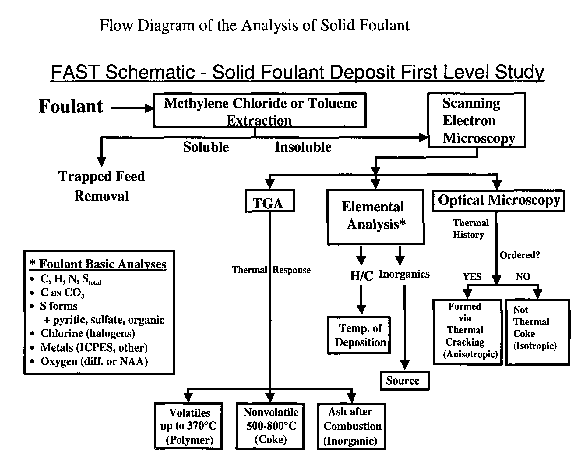
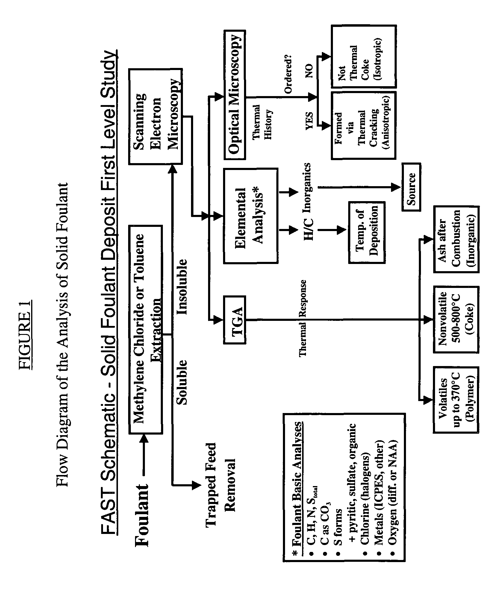
The present invention is a method to identify a refinery solid foulant of unknown composition including the following steps: obtaining a solid foulant sample, removing trapped feed from the sample with a solvent to obtain an insoluble sample, scanning the insoluble sample with a scanning electron microscope and energy dispersive x-rays, performing a thermal gravimetric analysis including an ash test on the insoluble sample to determine the presence of polymer, coke and inorganic elements, performing an elemental analysis on the insoluble sample for the elements carbon, hydrogen, sulfur, nitrogen, halogens, and metals, performing an optical microscopy on the insoluble sample to determine the presence of wax, asphaltenes, anisotropic coke and isotropic coke, and identifying the solid foulant.

Description

[0001]This application claims the benefit of U.S. Provisional Application No. 60 / 588,743 filed Jul. 16, 2004.BACKGROUND OF THE INVENTION[0002]The present invention is a method to identify the chemical composition of an unknown refinery solid foulant deposit. This invention provides a procedure, which enables refinery and support laboratory personnel to better coordinate the diagnosis and solution of the most common hydrocarbon fouling problems in refining by having an accurate understanding of what the foulant material is. Although the examples used in this report focus on refining, the protocol described is also fully applicable to chemical plant and upstream unit fouling analyses.[0003]Petroleum refining includes a number of different method units. Fouling of a method unit is caused by the accumulation of an unexpected phase in a method unit. This phase is often a solid that accumulates on the surfaces of the method equipment that is designed to handle flowing liquids or gases.[00...

Claims


Application Information

Patent Timeline
Patent Type & Authority Patents(United States)
IPC IPC(8): C10B43/14
CPCG01N17/008G01N33/28Y10T436/24Y10S436/805Y10S436/908
Inventor BRONS, GLENBROWN, LEO D.JOSHI, HIMANSHUKENNEDY, RAYMOND J.BRUNO, TOMRUDY, THOMAS M.
Owner EXXON RES & ENG CO
Learn More