
Motorcycle

a technology for motorcycles and motors, applied in the field of motorcycles, can solve problems such as negative impact on engine performance, and achieve the effect of improving engine performan

Inactive Publication Date: 2010-04-27
YAMAHA MOTOR CO LTD
View PDF14 Cites 8 Cited by
  • Summary
  • Abstract
  • Description
  • Claims
  • Application Information

AI Technical Summary

Benefits of technology

The invention is a motorcycle with a fuel injection valve that is positioned to improve engine performance. The fuel injection valve is located between the intake valve and the cylinder head, allowing for better air-fuel mixing. The motorcycle also includes a panel member that forms a stride part for the rider, as well as a throttle body and fuel injection valve that are positioned to maintain loading and unloading capabilities. The technical effects of the invention include improved engine performance and better air-fuel mixing without increasing the position of the panel member.

Problems solved by technology

In a motorcycle adopting a structure in which a fuel injection valve is stood and arranged in the downstream end of an intake passage extending from a cylinder head to the front of the vehicle, an injection direction of the fuel injection valve is oriented to a ceiling wall of an intake port and the fuel cannot be injected toward the essentially desirable umbrella back of an intake valve, which may negatively impact engine performance.

Method used


Image

  • Motorcycle
  • Motorcycle
  • Motorcycle

Examples


first embodiment

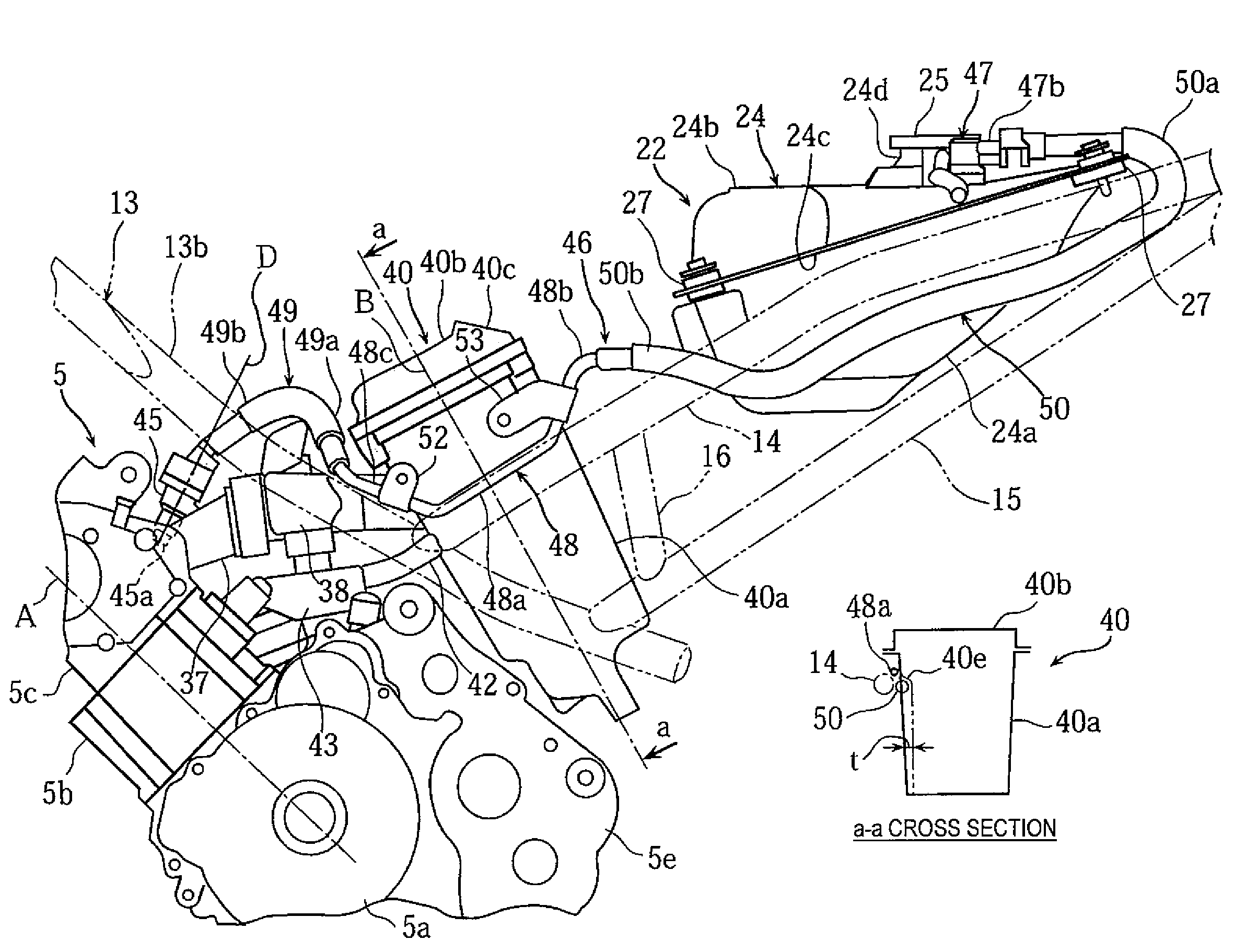
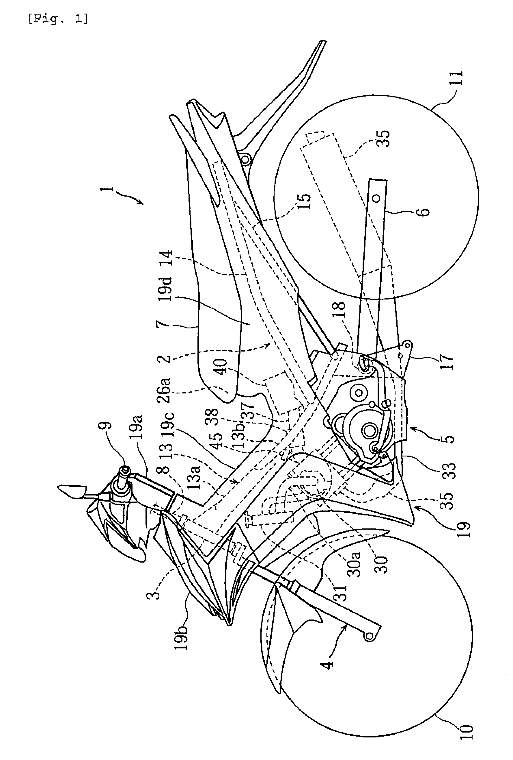
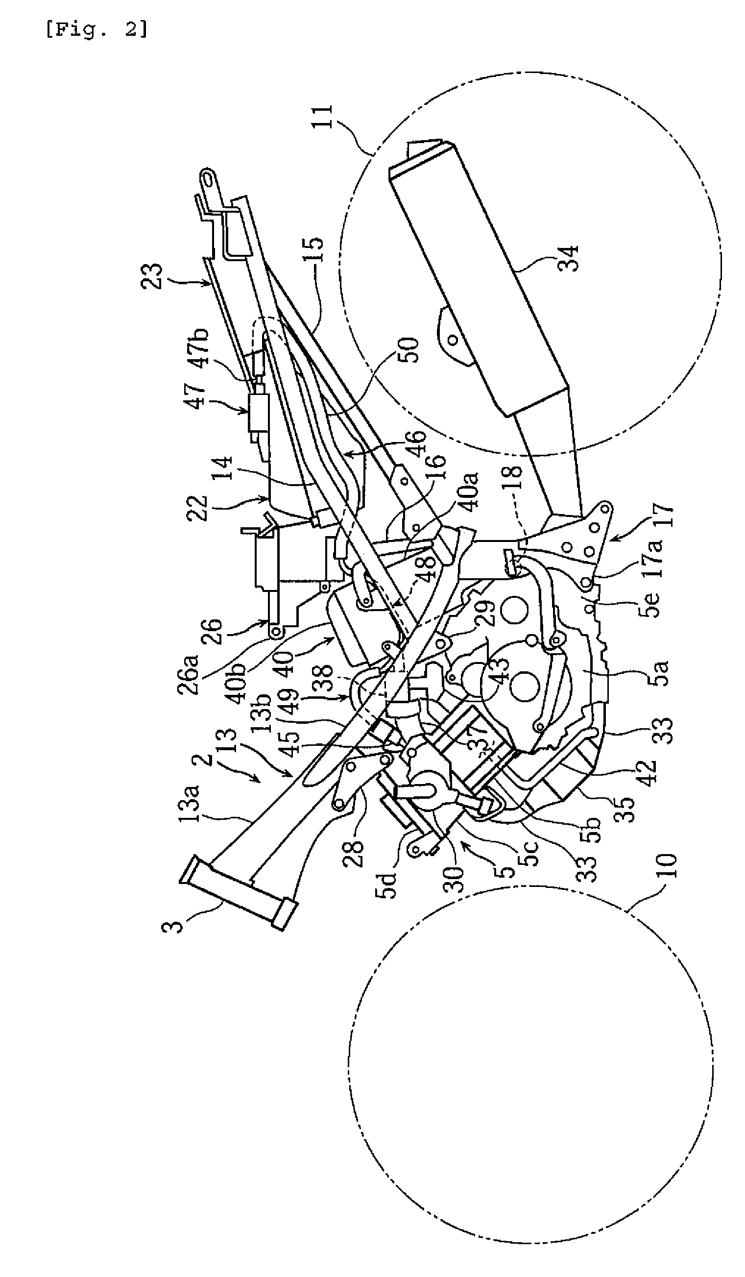
[0020]FIGS. 1-5 are diagrams describing a motorcycle according to the invention. The terms “forward”, “backward”, “left” and “right” in the following description mean forward, backward, left and right from the perspective of a rider sitting on the seat.

[0021]In the drawings, numeral 1 is a motorcycle comprising a vehicle body frame 2 of an under bone type, a front fork 4 pivoted by a head pipe 3 fixed in a front end of vehicle body frame 2, an engine 5 suspended and supported in the center of vehicle body frame 2, a rear arm 6 vertically swingably pivoted in the back side of engine 5 of vehicle body frame 2, and a seat 7 for two arranged on vehicle body frame 2.

[0022]A front wheel 10 is axially supported in the lower end of front fork 4 and a rear wheel 11 is axially supported in the back end of rear arm 6.

[0023]A steering shaft 8 is axially supported in head pipe 3 through a bearing (not shown). Front fork 4 is fixed in the lower end of steering shaft 8 and a steering handle 9 is f...

second embodiment

[0065]FIGS. 6 and 7 are diagrams describing a motorcycle according to the invention. In FIGS. 6 and 7, the same numerals as those of FIG. 2 show the same or corresponding parts.

[0066]In the motorcycle of the second embodiment, a frame member 60 connected to a head pipe 3 is displaced to one side of a vehicle width direction with respect to a vehicle body center line C passing through an axis line of head pipe 3.

[0067]In frame member 60, a leg shield (panel member) (not shown) for covering the upper, left and right sides of frame member 60 is arranged to coincide with vehicle body center line C.

[0068]In the lower side of frame member 60, an engine 5 is mounted to coincide with vehicle body center line C. An intake tube 37 connected to a cylinder head 5c of engine 5 extends backward to the other side of the vehicle width direction with respect to vehicle body center line C, and is connected to an air cleaner 40.

[0069]A fuel injection valve 45 is located in the other side of frame memb...


PUM


Abstract

A motorcycle with a fuel injection valve oriented to the umbrella back of an intake valve to improve engine performance. An engine is mounted in a lower portion of a leg shield panel member) that forms a stride part. An intake passage is connected to a forward-tilted cylinder head of the engine and extends backward in the lower side of the leg shield. A throttle body into which a throttle valve is built is interposed in the vicinity of an engine connection part of the intake passage. A fuel injection valve is disposed inside space surrounded by the throttle body, the cylinder head and the leg shield when viewed from the side of the motorcycle.

Description

RELATED APPLICATIONS[0001]This application claims the benefit of priority under 35 USC 119 of Japanese patent application no. 2005-302070, filed on Oct. 17, 2005, which application is hereby incorporated by reference in its entirety.BACKGROUND OF THE INVENTION[0002]1. Field of the Invention[0003]The present invention relates to a motorcycle having a stride part between a head pipe and a seat for facilitating the stride of a rider during loading and unloading.[0004]2. Description of Related Art[0005]Recent motorcycles adopt a method for controlling fuel supply by a fuel injection valve according to a run state in order to improve properties of exhaust gas, fuel efficiency or engine output. To arrange such a fuel injection valve, an intake passage connected to a cylinder head is extended to the front of the motorcycle and also is connected to an air cleaner. The fuel injection valve is stood in a substantially perpendicular orientation in the downstream end of the intake passage. See,...

Claims


Application Information

Patent Timeline
Patent Type & Authority Patents(United States)
IPC IPC(8): B62D61/02B62K11/04F02M37/00F02M55/02
CPCF02M69/044F02B61/02F01N3/22B62K2202/00Y02A50/20
Inventor MIYABE, TOSHIMASA
Owner YAMAHA MOTOR CO LTD
Learn More