
Integrated exhaust cylinder head

a technology of exhaust cylinder head and integrated exhaust, which is applied in the direction of cylinders, mechanical equipment, machines/engines, etc., can solve the problems of high thermal load, high thermal load, and high thermal load of exhaust manifolds that are integrated into cylinder heads (iem cylinder heads) and other problems, to achieve the effect of thermal degradation, thermal stress reduction of cylinder heads, and thermal loading reduction of integrated exhaust manifolds and neighboring components

Active Publication Date: 2013-03-07
FORD GLOBAL TECH LLC
View PDF7 Cites 42 Cited by
  • Summary
  • Abstract
  • Description
  • Claims
  • Application Information

AI Technical Summary

Benefits of technology

The patent text describes an approach to reducing heat damage to an engine and its components. This is achieved by incorporating coolant jackets into the cylinder head to remove heat through heat exchange with a circulated liquid coolant. The coolant jackets reduce thermal stresses on the cylinder head and other components, such as a turbocharger and emission control system. By providing a greater cooling surface area, the temperature of the exhaust gases and cylinder head components can be reduced, and high pressure exhaust blowdown pulses may be separated to improve engine performance. The cooling system also helps to prevent the formation of thermally degraded downstream components and sends an early over-temperature condition signal to an operator of the vehicle, allowing for timely intervention to prevent damage to the engine.

Problems solved by technology

Exhaust manifolds for internal combustion engines may be exposed to high thermal loads.
Exhaust manifolds that are integrated into cylinder heads (IEM cylinder heads) may experience particularly high thermal loading due to the heat transfer characteristics of the integrated design.
For example, IEM cylinder heads may channel exhaust to a single exhaust outlet port, which experiences a high thermal load during operation of the vehicle.
However, the inventors herein have recognized issues with the above described approach.
In one example, exhaust gases may be insufficiently cooled.
As a result, the cylinder head and / or other cylinder components may be thermally degraded too quickly.
Further, downstream engine or vehicle components, such as a turbocharger and / or an emission control system, may be thermally degraded.
During overlapping pulses of cylinders, one or more cylinders may receive high pressure exhaust blowdown from another cylinder, and thus engine efficiency may be reduced.

Method used


Image

  • Integrated exhaust cylinder head
  • Integrated exhaust cylinder head
  • Integrated exhaust cylinder head

Examples


Embodiment Construction

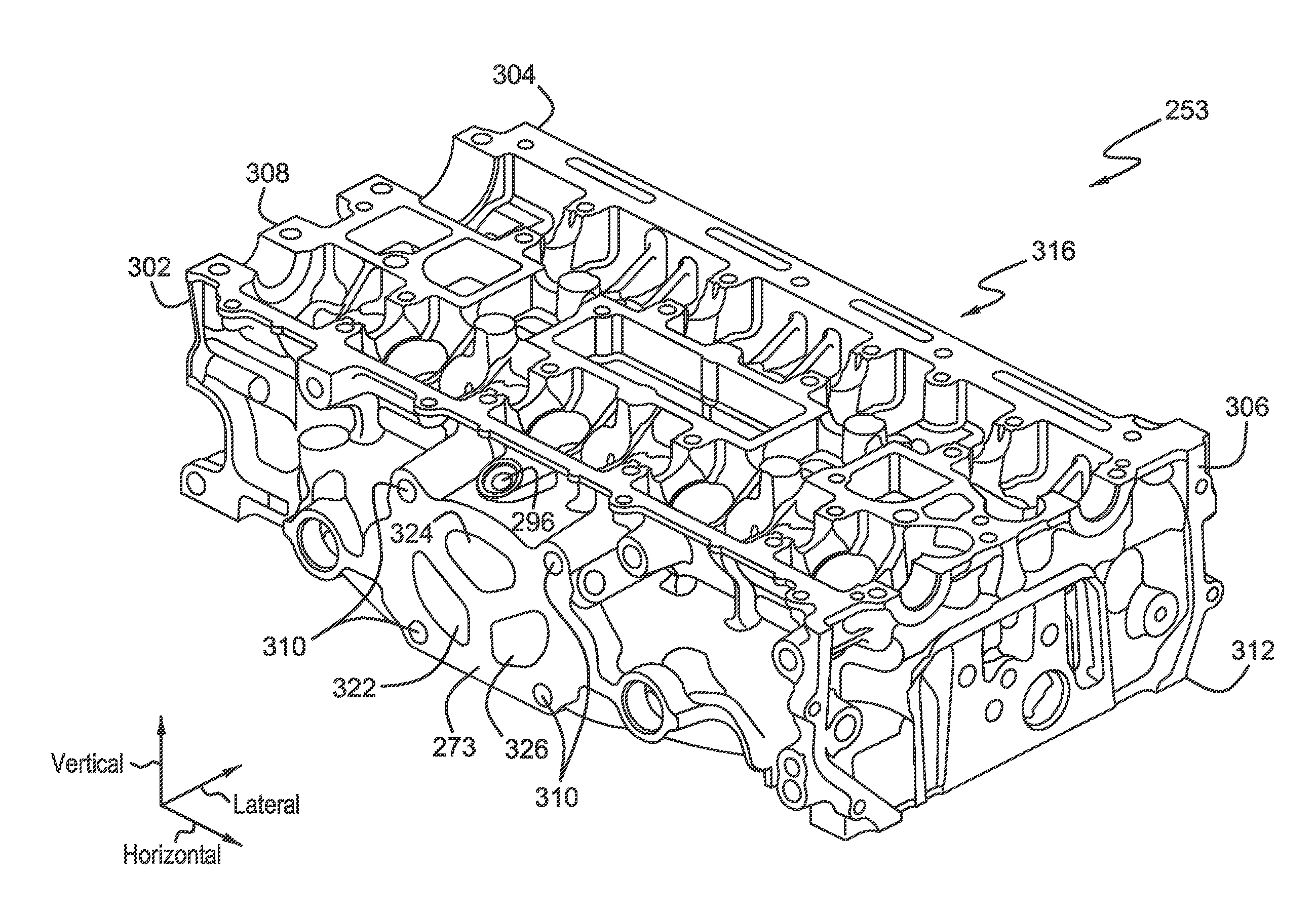
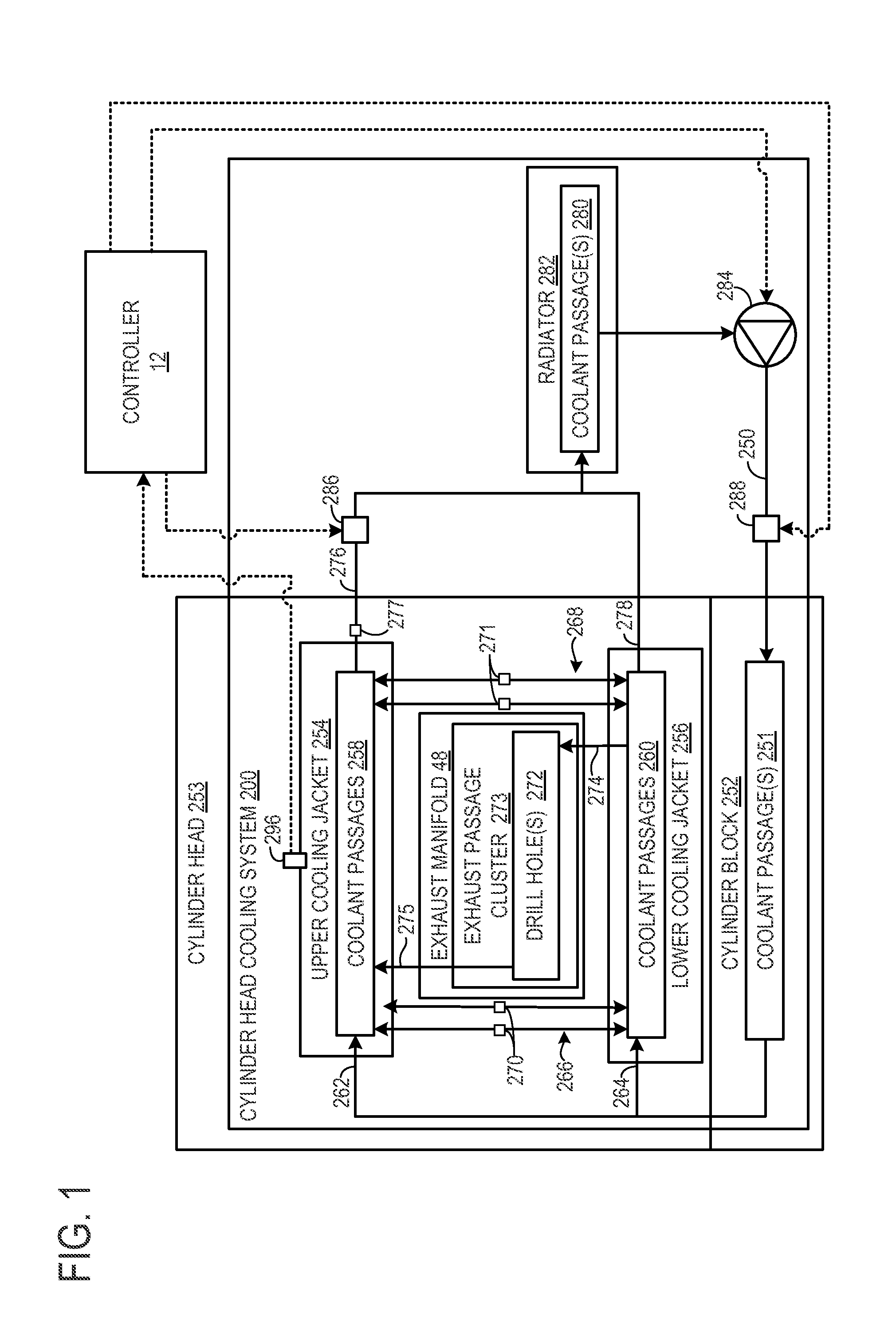
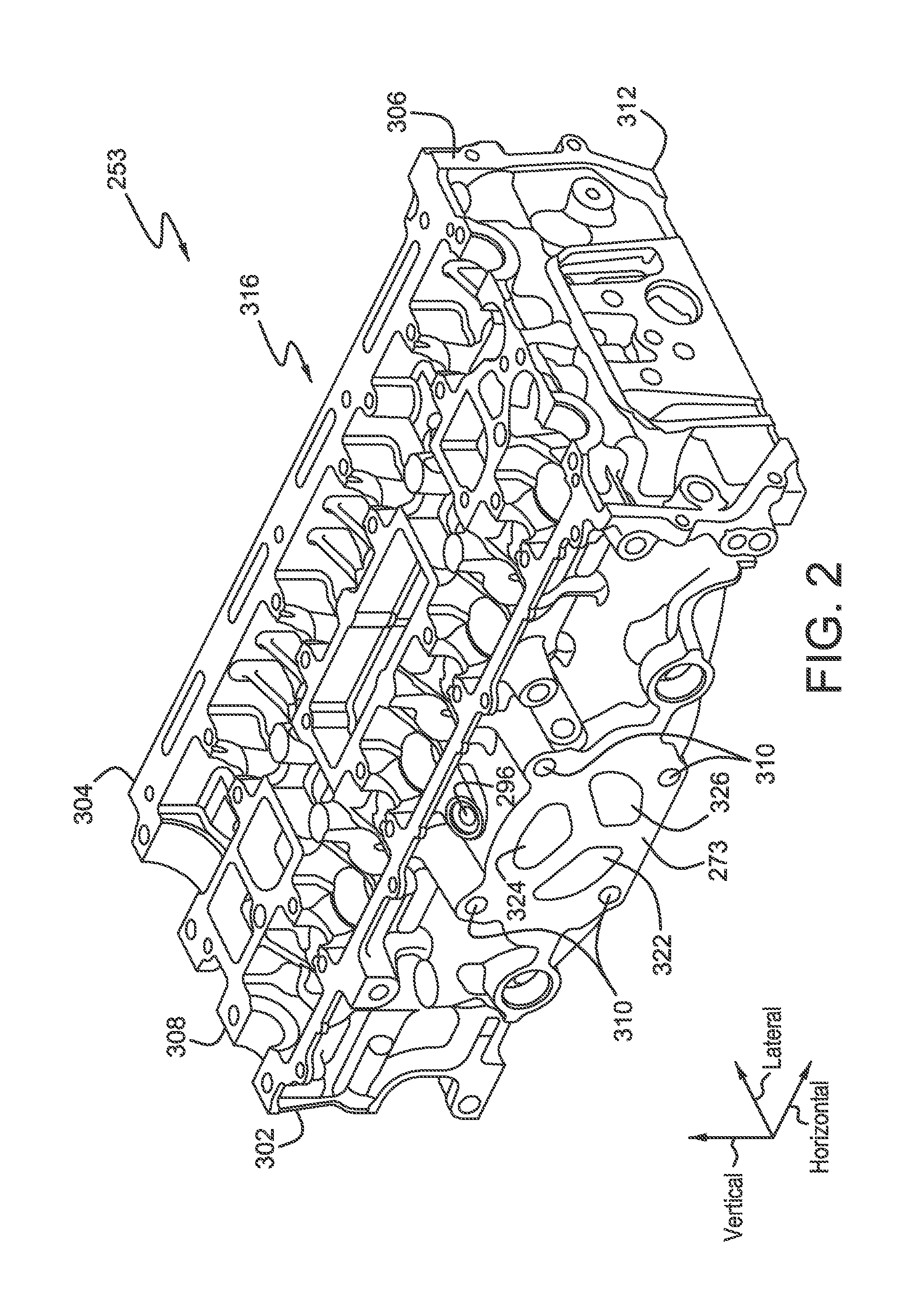
[0021]A cylinder head with an integrated exhaust manifold (IEM cylinder head) is described herein. The IEM cylinder head includes a cluster of exhaust outlet passages and coolant passages in communication with a coolant inlet and a coolant outlet. The exhaust passage cluster may include one or more drill holes disposed within the material linking and separating each exhaust passage in the cluster of exhaust passages. The one or more drill holes may be in communication with the coolant passages. The coolant inlet and outlet may be in communication with a cylinder head cooling system. The cylinder head cooling system may be configured to flow coolant through the coolant passages in the cylinder head and the drill holes in the exhaust passage cluster, such that liquid coolant may be circulated through the walls of the exhaust passage cluster, proximal to the exhaust face. In this way, improved cooling may be provided to the cluster of exhaust passages. Moreover, cooling of exhaust gase...


PUM


Abstract

An engine cooling system is provided. The engine cooling system includes a cylinder head including an integrated exhaust manifold that directs exhaust gases to an exhaust outlet port and a coolant passage surrounding the exhaust manifold. The engine cooling system further includes a cluster of separated exhaust passages for directing exhaust gases to the exhaust outlet port, the cluster including a drill hole disposed within material between the exhaust passages, the drill hole fluidically coupled to the coolant passage.

Description

BACKGROUND AND SUMMARY[0001]Exhaust manifolds for internal combustion engines may be exposed to high thermal loads. Exhaust manifolds that are integrated into cylinder heads (IEM cylinder heads) may experience particularly high thermal loading due to the heat transfer characteristics of the integrated design. For example, IEM cylinder heads may channel exhaust to a single exhaust outlet port, which experiences a high thermal load during operation of the vehicle.[0002]Thermal loading of an integrated exhaust manifold and neighboring components can be reduced by incorporating coolant jackets into the cylinder head. The coolant jackets with a coolant core formed therein can reduce the thermal stresses on the cylinder head caused by heat generated during engine operation. For example, a cylinder head having an integrated exhaust manifold is disclosed in U.S. Pat. No. 7,367,294. Upper and lower coolant jackets encompass a major portion of the cylinder head to remove heat from the cylinde...

Claims


Application Information

Patent Timeline
IPC IPC(8): F02F1/38F02F1/40F02F1/24
CPCF02F1/24F02F2001/247F02F1/40F02F1/243F02F1/36F02F1/242F01N3/046F01N13/105Y02T10/20F01P3/02F01P3/12F02F2001/245F02B3/06F02F1/4214F02F1/38Y02T10/12
Inventor BREWER, TODD JAYRIEGGER, JOHN CHRISTOPHERTALLIO, KEVIN V.
Owner FORD GLOBAL TECH LLC
Learn More