
Method and device for performing online aberrometry in refractive eye correction

a technology of aberrometry and refractive eye, applied in the field of methods and devices for correcting visual defects of the human eye, can solve problems such as lens correction

Inactive Publication Date: 2010-04-20
CARL ZEISS MEDITEC AG
View PDF8 Cites 1 Cited by
  • Summary
  • Abstract
  • Description
  • Claims
  • Application Information

AI Technical Summary

Benefits of technology

[0007]Therefore, the object of the present invention is to provide a method and a device which permit complete correction of all refractive visual defects, including the aberrations of the optical path in the defective eye.

Problems solved by technology

It is felt to be a disadvantage of the related art that the correction of the lenses takes place only on the basis of suboptimum data on the causes of the visual defects such as irregularities of the cornea surface or aberration in the optical path.

Method used


Image

  • Method and device for performing online aberrometry in refractive eye correction
  • Method and device for performing online aberrometry in refractive eye correction
  • Method and device for performing online aberrometry in refractive eye correction

Examples


Embodiment Construction

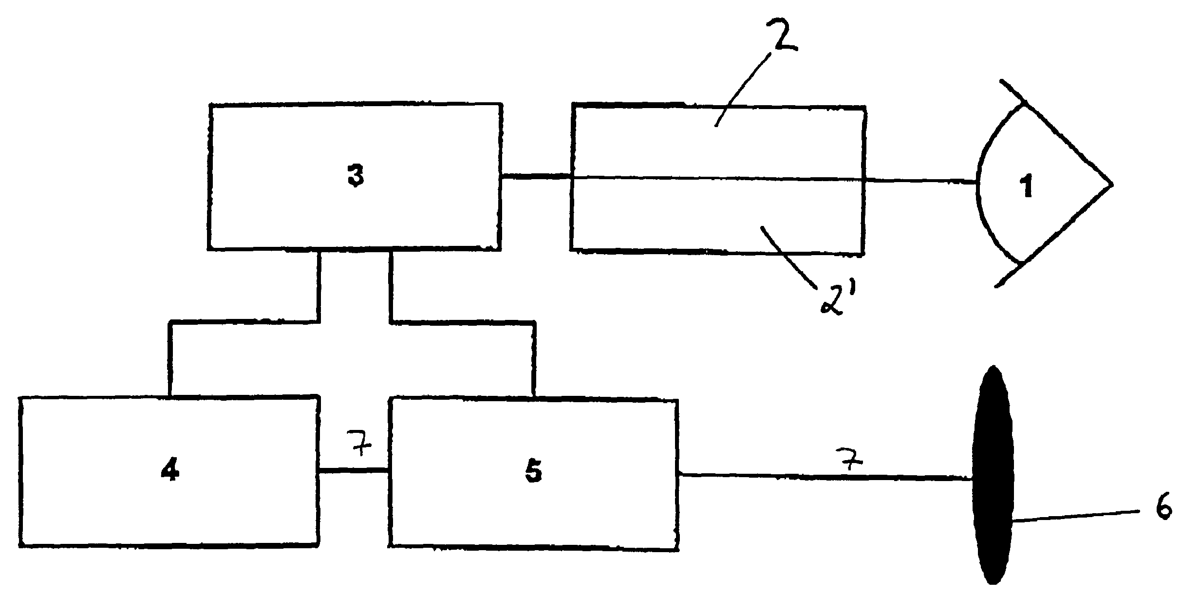
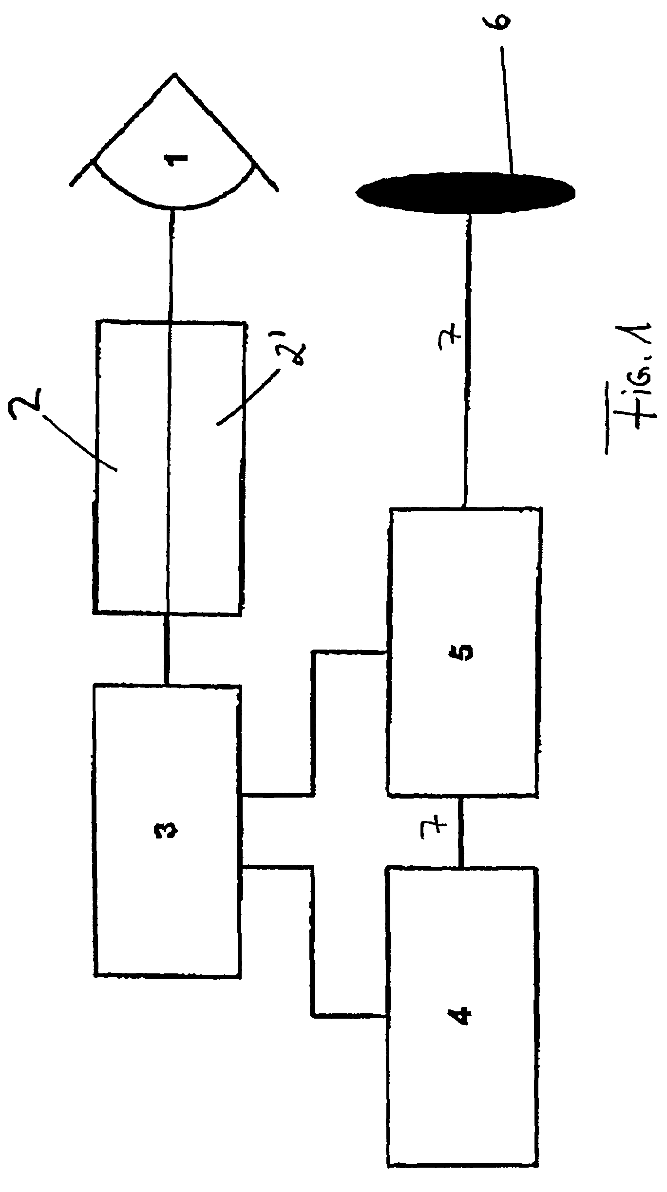
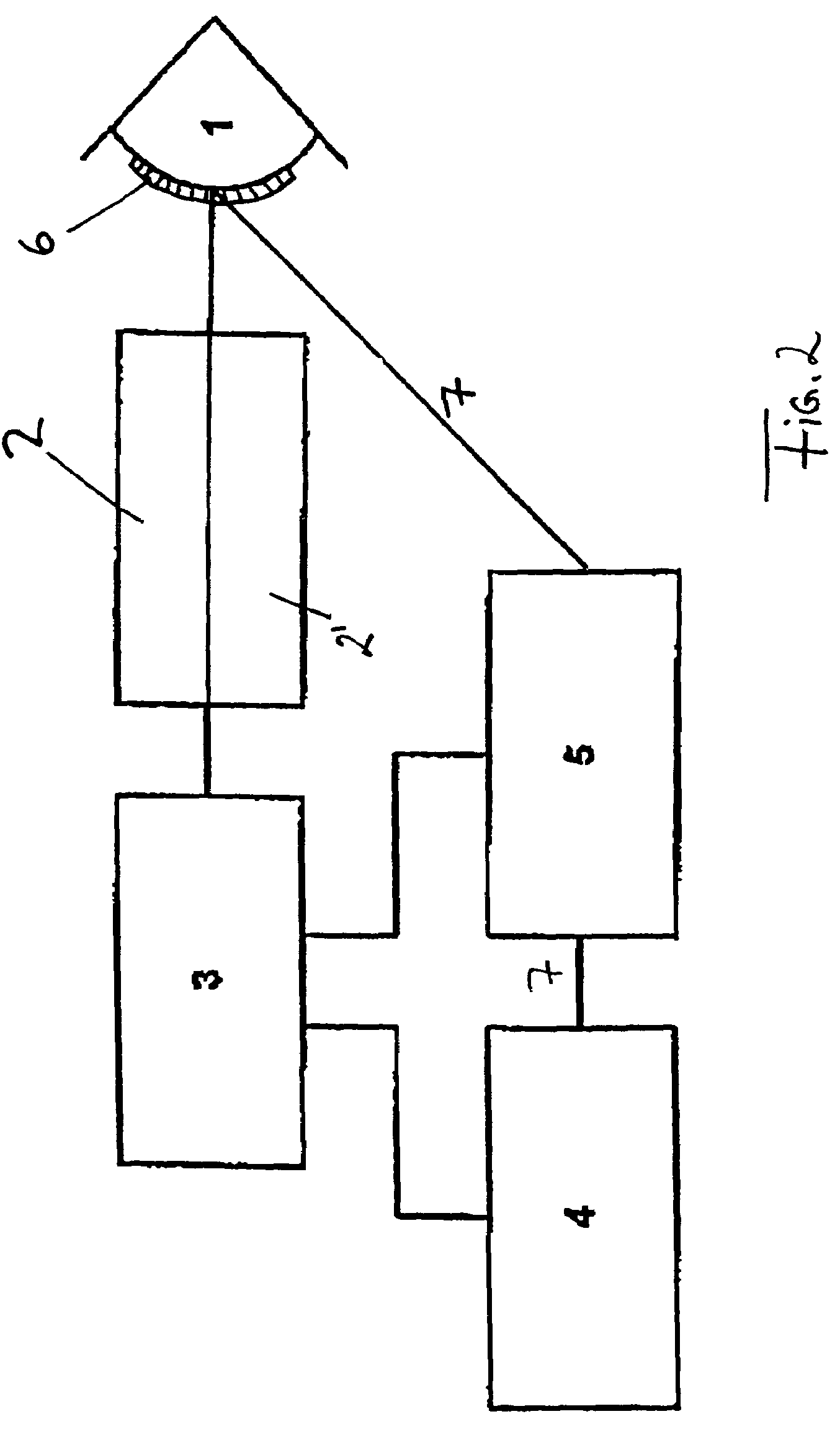
[0039]FIG. 1 depicts a block diagram for an exemplary embodiment of a device according to the present invention for correcting visual defects of an eye on a lens. A wavefront analyzer unit 2 and a topography analyzer unit 2′ are connected to a control unit 3. Control unit 3 is connected to a laser 4 and to a beam modification device 5 via A bus. A lens 6 is depicted downstream of beam modification device 5. An eye 1 is shown upstream of wavefront analyzer unit 2 and topography analyzer unit 2′.

[0040]In the operating state, the beams of wavefront analyzer unit 2 and topography analyzer unit 2′ scan eye 1 and transmit the obtained signals to control unit 3. The beams which are used here are preferably beams of a coherent light source, especially preferably beams of an IR diode or of a green laser. In control unit 3, the signals are processed and the ideal optical system for this eye 1 is calculated. In the depicted case, an ideal lens 6 is calculated here as element of the optical sys...


PUM

PropertyMeasurementUnit
visual defectsaaaaaaaaaa
optical pathaaaaaaaaaa
refractive visual defectsaaaaaaaaaa

Abstract

This invention relates to a method and a device for the complete correction of sight defects in the human eye. Combinations of measuring, and processing methods are described which when applied as disclosed in the invention, make it possible to fully correct sight defects in the human eye. Measuring methods are used which can precisely scan the surface of the cornea and also register other imaging defects in the light path up to the retina. Computer-aided of said measuring results determined when combined with calculation of ideally corrected ocular lenses (for example after cataract operations) or ideally corrected surfaces of the cornea opens up the possibility of manufacturing a patient-specific lens and / or achieving ideal correction of the cornea using preferably a topography-supported spot-scanning-excimer laser system.

Description

CROSS-REFERENCE TO RELATED APPLICATIONS[0001]This application is a continuation of U.S. patent application Ser. No. 09 / 807,227 of Jul. 2, 2001, which is now U.S. Pat. No. 6,848,790 B1, issued Feb. 1, 2005. U.S. patent application Ser. No. 09 / 807,227 was filed as a national phase application of International Patent Application Serial No. PCT / EP00 / 07821, filed Aug. 11, 2000.BACKGROUND OF THE INVENTION[0002]The present invention relates to a method and a device for correcting visual defects of the human eye.[0003]In ophthalmology, it is known to shape the cornea by ablation of tissue in the case of amblyopia. In this context, the data on the aberration in the optical path of the eye is obtained by questioning the patient about his / her subjective impression of vision on the basis of corrections via standardized corrective lenses in front of the eye of the patient. Besides, methods exist for measuring the outer contour of the eye with the assistance of stripe- or ring-projection systems ...

Claims


Application Information

Patent Timeline
Patent Type & Authority Patents(United States)
IPC IPC(8): A61B3/10A61B18/20A61F2/14A61F9/007A61F9/013A61N5/06B23K26/06B23K26/064G01J9/00
CPCA61B3/1015A61F9/013B23K26/06B23K26/064B23K26/0665G01J9/00A61F9/008B23K26/0648
Inventor DICK, MANFREDSCHROEDER, ECKHARDFIEDLER, JOOACHIM
Owner CARL ZEISS MEDITEC AG
Learn More