
Electric power steering apparatus

a technology of electric power steering and steering shaft, which is applied in the direction of steering initiation, instruments, vessel construction, etc., can solve the problems of low reliability of the estimated value of the motor rotational angle, the difficulty of controlling, and the inability to execute control based on the detection signal of such malfunctioning rotational angle sensors. achieve the effect of high reliability

Active Publication Date: 2010-04-13
TOYOTA JIDOSHA KK
View PDF17 Cites 29 Cited by
  • Summary
  • Abstract
  • Description
  • Claims
  • Application Information

AI Technical Summary

Benefits of technology

The invention provides a highly reliable electric power steering apparatus that drives an electric motor to produce steering assist torque through sensorless control. The apparatus includes a steering mechanism, an electric motor, and a motor control means for controlling the rotation of the electric motor based on the steering operation of the driver. The apparatus also includes a rotational angle sensor that detects the rotational angle of the electric motor, and a rotational angle estimation means for estimating the rotational angle of the electric motor when the sensor malfunctions. The assist control means changes the control manner for causing the electric motor to produce the steering assist torque based on the information obtained from the sensor. The apparatus can enhance the reliability of the electric power steering apparatus and improve safety.

Problems solved by technology

Accordingly, if a malfunction occurs in a rotational angle sensor that detects the rotational angle of the electric motor, it becomes difficult to execute the control.
However, executing the control based on a detection signal from such malfunctioning rotational angle sensor is not as reliable as it should be.
If the electric motor is rotated at such a low speed, the reliability of the estimated value of the motor rotational angle is low.
Accordingly, if the electric motor of the electric power steering apparatus is driven under the sensorless control without taking any measures, the target assist torque is not achieved.
In some cases, a reverse assist torque may be produced, that is, an assist torque may be undesirably applied in the direction opposite to the direction in which the target assist torque should be applied.

Method used


Image

  • Electric power steering apparatus
  • Electric power steering apparatus
  • Electric power steering apparatus

Examples


first embodiment

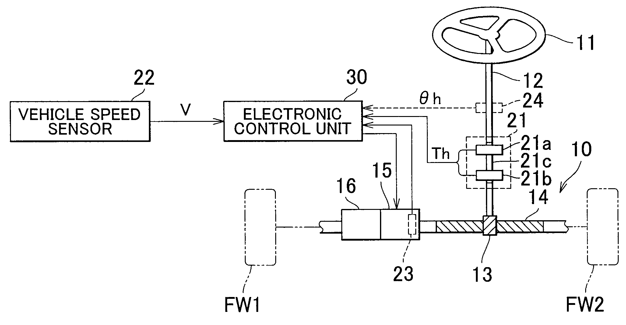
[0103]Hereafter, an electric power steering apparatus for a vehicle according to each embodiment of the invention will be described with reference to the accompanying drawings. FIG. 1 is a view schematically showing an electric power steering apparatus for a vehicle according to the invention.

[0104]The electric power steering apparatus for a vehicle mainly includes a steering mechanism 10 that steers steering wheels of a vehicle in response to the turning operation of a driver's steering wheel 11; an electric motor 15 that is fitted to the steering mechanism 10 and that produces a steering assist torque; and an electronic control unit 30 that controls the operation of the electric motor 15 in response to the turning operation of the driver's steering wheel 11.

[0105]The electric power steering apparatus includes a steering shaft 12 that is connected, at its upper end, to the driver's steering wheel 11 so as to rotate together with the driver's steering wheel 11. A pinion gear 13 is c...

second embodiment

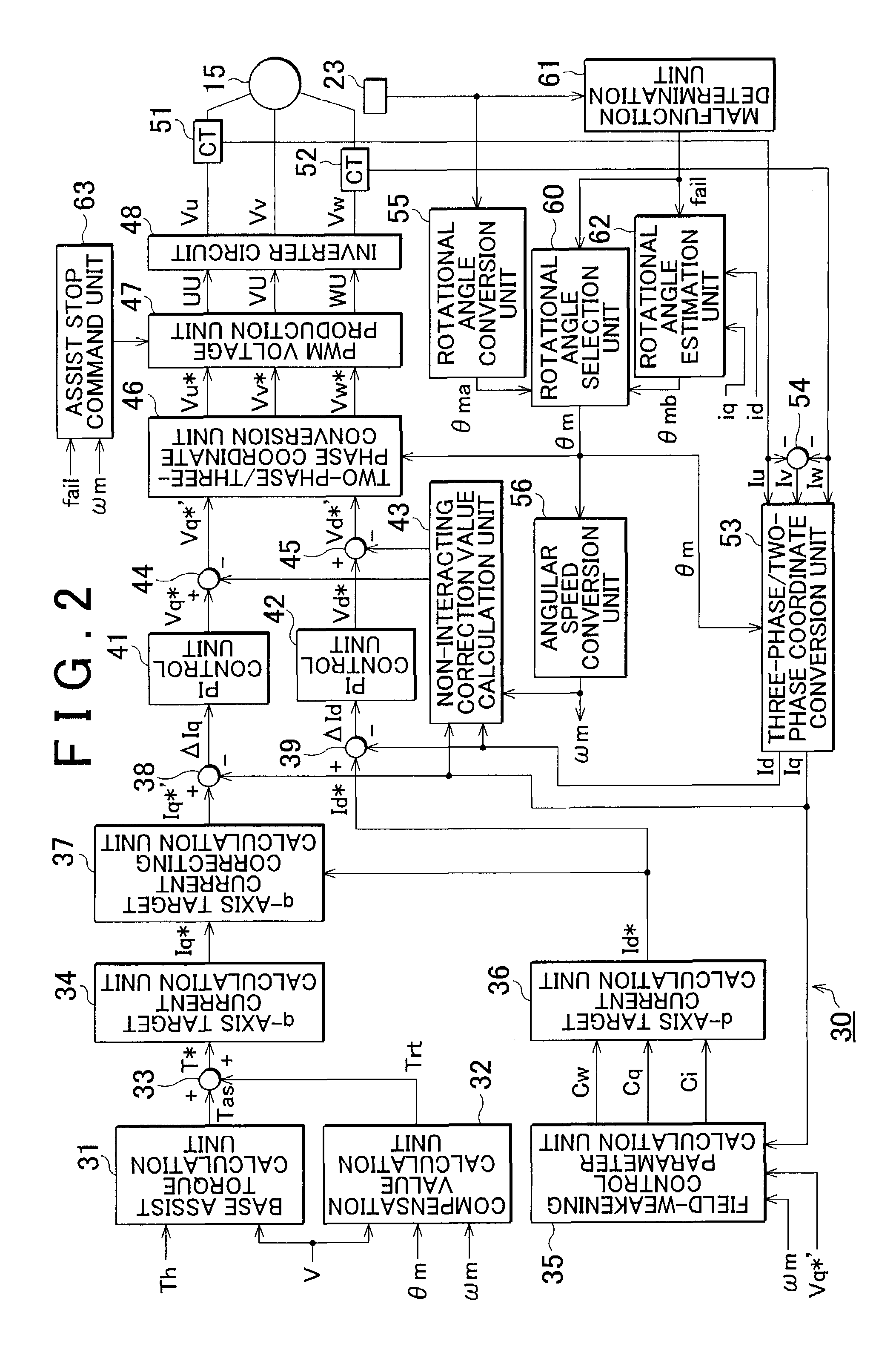
[0151]The assist gain change command unit 64 receives the information concerning the motor rotational angular speed ωm from the angular speed conversion unit 56, and receives a sensor malfunction signal “fail” from the malfunction determination unit 61 when it is determined that a malfunction has occurred in the rotational angle sensor 23. As described above, the deviation of the estimated rotational angle θmb from the actual rotational angle decreases as the motor rotational angular speed ωm increases, and increases as the motor rotational angular speed ωm decreases. Therefore, according to the invention, the correction gain K1x, with which the steering assist torque is decreased as the motor rotational angular speed ωm decreases, is set to prevent the deviation of the estimated rotational angle θmb from the actual rotational angle from exerting a great influence on the steering assist torque.

[0152]As shown in FIG. 15A, the correction gain K1x is set to a smaller value as the motor...

third embodiment

[0156]The electronic control unit 30 according to the invention is provided with a steering speed detection unit 65 and an assist stop command unit 63′. The steering speed detection unit 65 receives a signal indicating the steering angle θh from the steering angle sensor 24, and calculates the temporal change (the derivative value) in the steering angle θh to obtain the steering speed ωh. The steering speed detection unit 65 transmits the information concerning the calculated steering speed ωh to the assist stop command unit 63′. Because the driver's steering wheel 11 and the electric motor 15 are mechanically connected to each other by the steering mechanism 10, the steering speed and the motor rotational angular speed are proportional to each other. Accordingly, the assist stop command unit 63′ receives a signal indicating the steering speed ωh instead of a signal indicating the motor rotational angular speed ωm, thereby determining whether the motor rotational angular speed ωm be...


PUM


Abstract

When it is determined that a malfunction has occurred in a rotational angle sensor, an electronic control unit changes the control manner from the normal assist control to the sensorless assist control. In the sensorless assist control, an assist stop command unit receives the information concerning the motor rotational angular speed ωm from an angular speed conversion unit. Then, the motor rotational angular speed ωm is compared with the threshold value ωm1. If the motor rotational angular speed ωm is equal to or higher than the threshold value ωm1, an assist enabling signal is transmitted to a PWM voltage production unit to continue the power assist. On the other hand, if the motor rotational angular speed ωm is lower than the threshold value ωm1, a stop command signal is transmitted to the PWM voltage production unit to stop the power assist.

Description

INCORPORATION BY REFERENCE[0001]The disclosure of Japanese Patent Application No. 2006-218313 filed on Aug. 10, 2006 including the specification, drawings and abstract is incorporated herein by reference in its entirety.BACKGROUND OF THE INVENTION[0002]1. Field of the Invention[0003]The invention relates to an electric power steering apparatus which is provided with an electric motor and which assists a turning operation of a driver's steering wheel performed by a driver.[0004]2. Description of the Related Art[0005]There is an electric power steering apparatus for a vehicle that detects a steering torque applied to a steering wheel which is turned by a driver (hereinafter, referred to as a “driver's steering wheel”) and that causes an electric motor to produce an assist torque based on the detected steering torque. For example, in an electric power steering apparatus described in Japanese Patent Application Publication No. JP-2003-26020 (JP-A-2003-26020), a controller calculates a t...

Claims


Application Information

Patent Timeline
Patent Type & Authority Patents(United States)
IPC IPC(8): B62D5/04
CPCB62D5/046B62D5/049B62D5/0484B62D5/0463
Inventor YAMASHITA, MASAHARUKASAI, EIJIYAMAZAKI, IPPEIFUJITA, SHUJI
Owner TOYOTA JIDOSHA KK
Learn More