Scanning probe apparatus

a probe apparatus and scanning technology, applied in the direction of mechanical measurement arrangements, mechanical roughness/irregularity measurements, instruments, etc., can solve the problems of deterioration of the drive element of the counterweight, inability to cancel the inertial force, and causing the scanning stage to be refreshed by replacemen

Inactive Publication Date: 2010-03-30
CANON KK
View PDF32 Cites 16 Cited by
  • Summary
  • Abstract
  • Description
  • Claims
  • Application Information

AI Technical Summary

Benefits of technology

[0023]A principal object of the present invention is to provide a scanning probe apparatus capable of properly cancelling inertial force generated with respect to a scanning stage and a drive stage while considerably alleviating expense in time and effort such that an operator makes correction every time the scanning stage or the drive stage is replaced.
[0038]According to the present invention, it is possible to provide a scanning probe apparatus capable of properly cancelling inertial force generated with respect to a scanning stage and a drive stage without requiring expense in time and effort such that an operator makes correction every time the scanning stage or the drive stage is replaced.

Problems solved by technology

In this case, however, when a scanning stage including the above described movable portions (counterweight, balance weight) for cancelling inertial force is used, the following problem is caused to occur.
When only the scanning stage is replaced while leaving the movable portions as they are, a balance relationship with the counterweight cannot be maintained, so that a desired cancellation of inertial force cannot be effected in some cases.
For this reason, when the SPM is continuously used by replacing only the scanning stage, such a phenomenon that deterioration of the drive element for the counterweight occurs and on the other hand, the scanning stage is refreshed by replacement is caused to occur.
As a result, an amount of displacement with respect to an applied voltage is different between the drive element for the counterweight and the drive element for the scanning stage, so that it is further difficult to cancel the inertial force generated with respect to the scanning stage.

Method used


Image

  • Scanning probe apparatus
  • Scanning probe apparatus
  • Scanning probe apparatus

Examples


embodiment 1

[0054]In Embodiment 1, the present invention is applied so as to constitute a replaceable scanning stage used in a scanning probe apparatus.

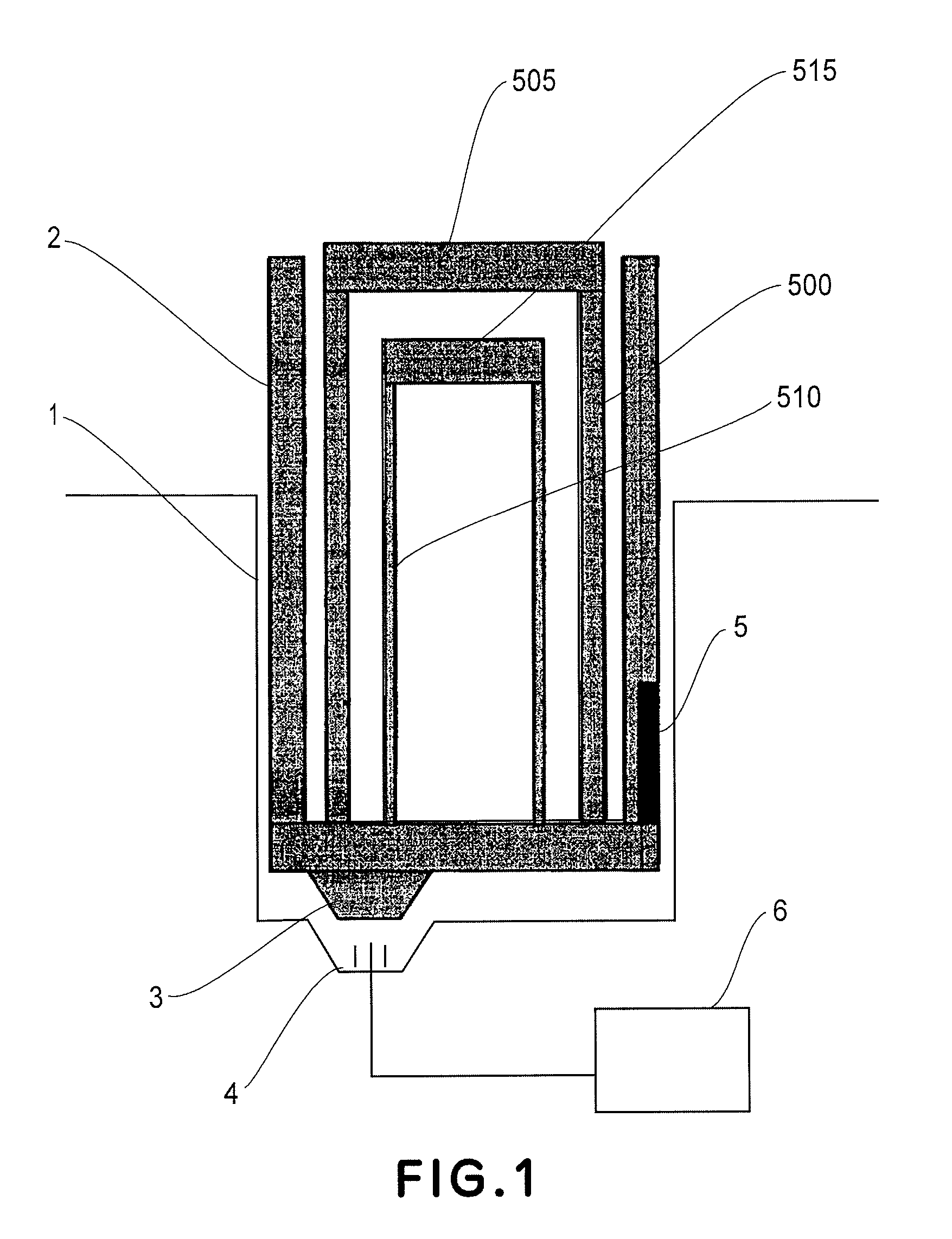
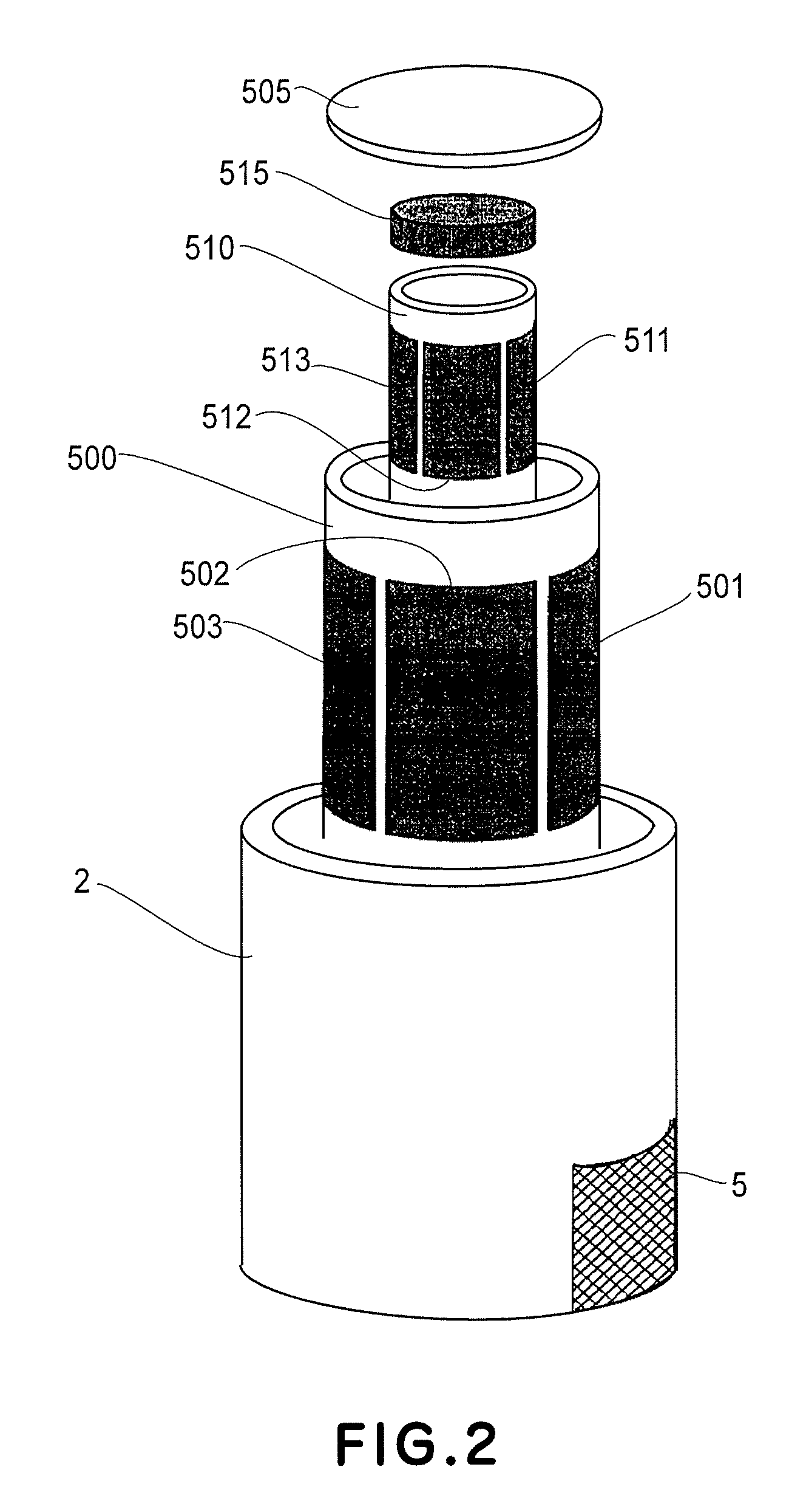
[0055]FIG. 1 is a schematic sectional view of a scanning stage which is replaceable with respect to a main assembly of a scanning probe apparatus in this embodiment. FIG. 2 is a schematic view for illustrating the constitution of the scanning stage used in the scanning probe apparatus illustrating the constitution of the scanning stage used in the scanning probe apparatus in this embodiment.

[0056]Referring to FIGS. 1 and 2, the scanning probe apparatus includes a recess 1 provided to a main assembly of the scanning probe apparatus; a bottom supporting table 2; an electric connector 3 provided to the bottom supporting table; an electric connector 4, to be connected to the electric connector 3, provided at the recess of the main assembly of the scanning probe apparatus; a drive circuit 5 for driving a scanning piezoelectric element and a counter p...

embodiment 2

[0073]In Embodiment 2, a replaceable scanning mechanism which is different from that in Embodiment 1 and is usable in the scanning probe apparatus of the present invention will be described.

[0074]FIG. 4 and FIG. 5(a) to 5(c) are schematic views showing a constitution of the scanning mechanism in this embodiment.

[0075]In these figures, a scanning mechanism 400 includes a scanning mechanism holding table 401, a drive element base 402, drive elements 403, 404 and 405, drive element holding members 406 and 407, a sample holding member 408, a weight member 409, and a drive circuit 410 for driving the scanning piezoelectric element and the counter piezoelectric element.

[0076]In this embodiment, at an outer portion of the drive element base 402, an IC chip including the drive circuit 410 is provided as shown in FIGS. 4 and 5(a), so that these members are integrally replaceable from the scanning mechanism holding table 401 on the main assembly side of the scanning probe apparatus. More spec...

embodiment 3

[0082]In Embodiment 3, a constitution of a scanning probe apparatus including a probe drive stage and a sample stage both of which are provided with a drive circuit will be described. In this embodiment, as the sample stage, a sample stage having the same constitution as that in Embodiment 1 is used.

[0083]Further, to the probe drive stage, a basic constitution of the sample stage in Embodiment 1 is also applied so as to constitute such a probe drive stage that it is provided with a drive element for moving a probe holding table and a movable portion for cancelling inertial force generated during movement of the probe holding table. Further, the probe drive stage is constituted so that the movable portion and the drive element including the probe holding stage are integrally replaceable from the main assembly of the scanning probe apparatus.

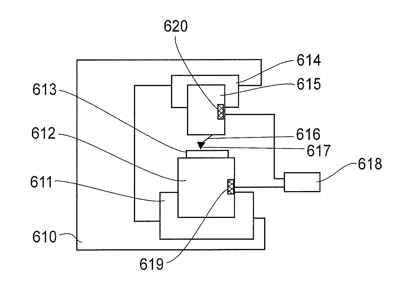
[0084]FIG. 6 is a schematic view for illustrating a constitution of the scanning probe apparatus in this embodiment.

[0085]Referring to FIG. 6, th...


PUM

PropertyMeasurementUnit
scanning frequencyaaaaaaaaaa
frequencyaaaaaaaaaa
frequencyaaaaaaaaaa

Abstract

A scanning probe apparatus for obtaining information of a sample, recording information in the sample, or processing the sample with relative movement between the sample and the apparatus, the apparatus is constituted by a probe; and a scanning stage including a drive element for moving a sample holding table for holding the sample and a movable portion movable in a direction in which an inertial force generated during movement of the sample holding table is cancelled. The scanning stage further includes a drive circuit for driving the scanning stage and is detachably or replaceably mountable to a main assembly of the apparatus.

Description

FIELD OF THE INVENTION AND RELATED ART[0001]The present invention relates to a scanning probe apparatus ordinarily utilizing a scanning probe microscope (SPM).[0002]Particularly, the present invention relates to a scanning probe apparatus for obtaining information of a sample, recording information in the sample, or processing the sample with relative movement between a probe and the sample.[0003]In recent years, a scanning tunneling microscope (STM) capable of observing a surface of an electroconductive substance with resolution of nanometer or below has been developed. Further, an atomic force microscope (AFM) or the like capable of observing a surface of an insulating substance or the like with resolution similar to that of the STM has also been developed.[0004]As a further developed type thereof, a scanning near-field optical microscope (SNOM) or the like for observing a surface state of a sample by utilizing evanescent light leaking from a minute opening at a sharp tip of a pro...

Claims


Application Information

Patent Timeline
Patent Type & Authority Patents(United States)
IPC IPC(8): G01N23/00G01B21/30G01Q10/00G01Q10/04
CPCG01Q70/04B82Y35/00
Inventor YASUDA, SUSUMUSEKI, JUNICHIKUSAKA, TAKAOYOSHIMATSU, NOBUKI
Owner CANON KK
Why Eureka
Try Eureka