Method of joining members having different thermal expansion coefficients

a technology of thermal expansion coefficient and joining member, which is applied in the direction of manufacturing tools, non-electric welding apparatus, and welding apparatus, etc., can solve the problems of insufficient durability of the joining layer and the fragil and achieve the effects of reducing heating, reducing stress, and rigidity of the joining layer

Inactive Publication Date: 2010-03-30
HONDA MOTOR CO LTD
View PDF11 Cites 9 Cited by
  • Summary
  • Abstract
  • Description
  • Claims
  • Application Information

AI Technical Summary

Benefits of technology

[0009]Another object of the present invention is to provide a method of joining members having different thermal expansion coefficients, by which a joining layer having excellent durability to a thermal cycle consisting of heating and cooling steps, can be obtained.
[0014]Furthermore, in the method according to the first aspect of the invention, the Ag particles and the Ag foil or the metal foil having a smaller modulus of longitudinal elasticity than that of Ag are placed between the two members and heated. Therefore, the rigidity of the joining layer thus formed can be reduced. Hence, according to the method of the first aspect of the invention, when the two members thus joined are exposed to a thermal cycle consisting of heating and cooling steps, they can absorb distortion to be produced by the thermal cycle and simultaneously suppress the stress to be generated. As a result, the members can acquire excellent durability to the thermal cycle.
[0021]Furthermore, in the method according to the second aspect of the invention, the wax material is formed of a powder mixture containing the first Ag particles, and the second Ag particles or particles of a metal having a smaller modulus of longitudinal elasticity than that of Ag. The second Ag particles or the particles of a metal have an average particle diameter of 20 μm or more are contained in a volume fraction of 10 to 40% relative to the total volume of the powder mixture. Therefore, the rigidity of the joining layer formed by placing the wax material between two members, followed by heating can be reduced. Hence, according to the method of the second aspect of the invention, when the two members joined are exposed to a thermal cycle consisting of heating and cooling steps, they can absorb distortion to be produced by the thermal cycle and simultaneously suppress the stress to be generated. As a result, the members can acquire excellent durability to the thermal cycle.

Problems solved by technology

However, when the pure Ag is melted by heating to the melting point of Ag, Ag and other metals are reacted to form alloys, with the result that the joining layer becomes fragile.
Thus, when the members whose thermal expansion coefficients are smaller than that of Ag are repeatedly subjected to a thermal cycle consisting of heating and cooling steps, the joining layer may not show sufficient durability to the thermal cycle because of the difference in thermal expansion coefficient between the joining layer and the members.

Method used


Image

  • Method of joining members having different thermal expansion coefficients
  • Method of joining members having different thermal expansion coefficients
  • Method of joining members having different thermal expansion coefficients

Examples


example 1

[0045]In this Example, Ag particles having an average particle diameter of 15 nm were prepared as the wax material 3. The Ag particles were coated with octadecanediol. The heat resistance temperature of the coating was about 220° C. Furthermore, an Ag foil having a thickness of 100 μm was prepared as the metal foil 4. Note that the modulus of longitudinal elasticity of Ag at room temperature is 82.7 GPa.

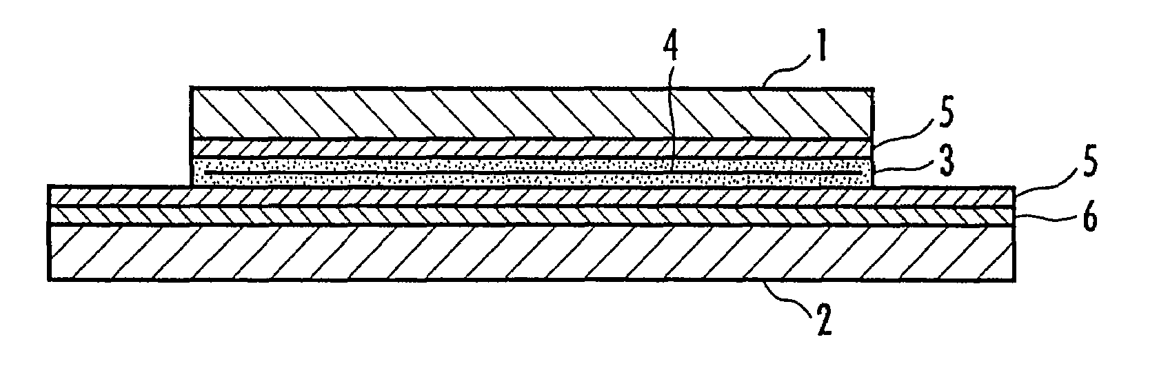
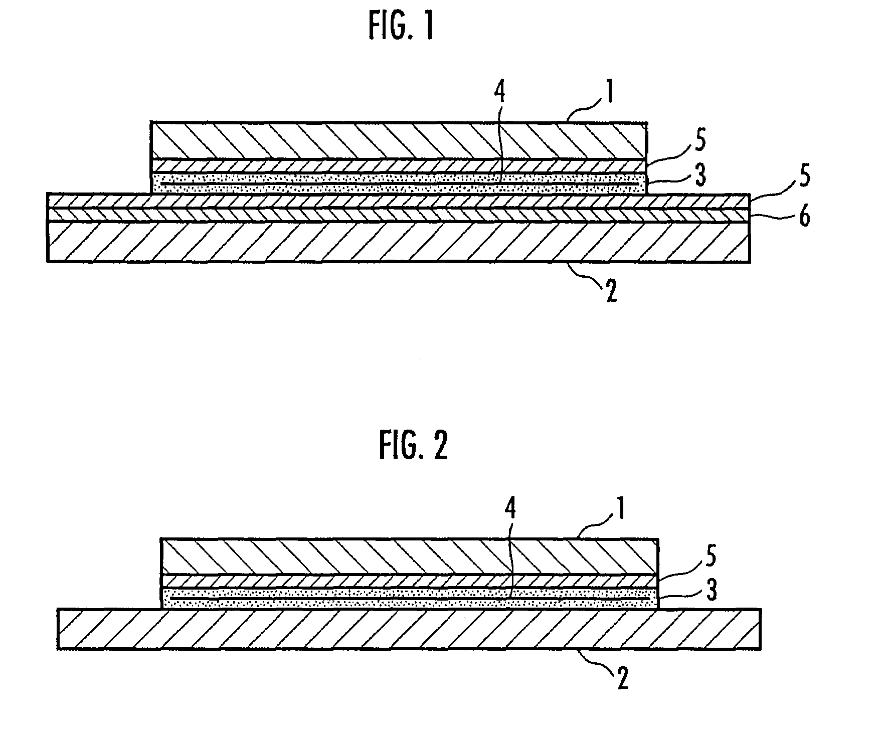
[0046]Subsequently, an Si chip of 10 mm×10 mm was prepared as the member 1 to be joined. The Si chip serving as the member 1 has the Ag coating layer 5 having a thickness of 50 nm and formed on a surface by vapor deposition, as shown in FIG. 1.

[0047]As the member 2 to be joined, an Al board of 20 mm×20 mm×5 mm was prepared. The Al board serving as the member 2 is formed of a material of Al050 board and has the Ni plating layer 6 on its surface, as shown in FIG. 1 and the Ag coating layer 5 of 120 nm in thickness is provided by vapor deposition on the Ni plating layer 6.

[0048]Note tha...

example 2

[0051]In this Example, the member (Si chip) 1 and the member (Al board) 2 were joined in substantially the same manner as in Example 1 except that an Ag coating layer (not shown), which was formed by vapor deposition on the surface of an Al foil of 100 μm in thickness, was used as the metal foil 4 in place of the Ag foil used in Example 1. Note that the modulus of longitudinal elasticity of Al at room temperature is 70.6 GPa, which is smaller than that (82.7 GPa) of Ag.

[0052]The members 1 and 2 thus joined were then subjected to the thermal cycle test in substantially the same manner as in Example 1 to evaluate durability to the thermal cycle. The results are shown in Table 1.

example 3

[0053]In this Example, the member (Si chip) 1 and the member (Al board) 2 were joined in substantially the same manner as in Example 1 except that an Ag coating layer (not shown), which was formed by vapor deposition on the surface of an Au foil of 100 μm in thickness, was used as the metal foil 4 in place of the Ag foil used in Example 1. Note that the modulus of longitudinal elasticity of Au at room temperature is 78.5 GPa, which is smaller than that (82.7 GPa) of Ag.

[0054]The members 1 and 2 thus joined were then subjected to the thermal cycle test in substantially the same manner as in Example 1 to evaluate durability to the thermal cycle. The results are shown in Table 1.


PUM

PropertyMeasurementUnit
average particle diameteraaaaaaaaaa
particle diameteraaaaaaaaaa
thicknessaaaaaaaaaa

Abstract

Provided is a method of joining members having different thermal expansion coefficients, capable of joining them at a temperature lower than the melting point of Ag to obtain a joining layer having excellent durability to a thermal cycle. First Ag particles 3 having an average particle diameter of 50 nm or less and an Ag foil 4 or metal foil 4 having a smaller modulus of longitudinal elasticity than that of Ag are placed between two types of members 1 and 2 at least one of which has a lower thermal expansion coefficient than that of Ag, heated to join the members 1 and 2. A wax material 3, which is a powder mixture containing first Ag particles having an average particle diameter of 50 nm or less and second Ag particles or particles of a metal (having a modulus of longitudinal elasticity than that of Ag) having an average particle diameter of 20 μm or more and being contained in a volume fraction of 10 to 40% relative to a total volume of the powder mixture, is placed between the two types of members 1 and 2, heated to join the members 1 and 2. The metal foil 4 and the particles of a metal have an Ag coating layer on a surface thereof. The first member 1 is formed of one type of material selected from the group consisting of Si, SiC, Al2O3, AlN and Si3N4 and the second member is formed of Al or Cu.

Description

BACKGROUND OF THE INVENTION[0001]1. Field of the Invention[0002]The present invention relates to a method of joining two types of members having different thermal expansion coefficients.[0003]2. Description of the Related Art[0004]In a conventional method of joining two types of members, it is known to join members, for example, different metals or a metal member and a ceramic member, with an Ag wax material.[0005]When pure Ag is used as the Ag wax material, the Ag wax material is placed as a joining layer between the members to be joined. However, when the pure Ag is melted by heating to the melting point of Ag, Ag and other metals are reacted to form alloys, with the result that the joining layer becomes fragile. Then, to join the members at a temperature lower than the melting point of Ag, use of an Ag wax material containing Ag particles in the order of nanometers has been investigated.[0006]As a composition containing the nanometer Ag particles, an Ag-powder mixture is known, w...

Claims


Application Information

Patent Timeline
Patent Type & Authority Patents(United States)
IPC IPC(8): B23K31/02
CPCB23K20/2333C04B37/02C04B37/026C04B2237/343C04B2237/365C04B2237/366C04B2237/368C04B2237/402C04B2237/407C04B2237/125C04B2237/123C04B2237/405C04B2237/55C04B2237/58C04B2237/86
Inventor OKAMOTO, KENJIKATO, TAKESHINONAKA, KENICHI
Owner HONDA MOTOR CO LTD
Why Eureka
Try Eureka