Eureka AIR delivers breakthrough ideas for toughest innovation challenges, trusted by R&D personnel around the world.

Three-way poppet valves with floating seat

a three-way poppet valve and seat technology, applied in the direction of valve operating means/release devices, suspensions, transportation and packaging, etc., can solve the problems of inability to manufacture and/or achieve pressure balance, inability to achieve the same degree of pressure balance, and inability to achieve superior controllability

Inactive Publication Date: 2010-03-23
STURMAN INDS
View PDF48 Cites 2 Cited by
  • Summary
  • Abstract
  • Description
  • Claims
  • Application Information

AI Technical Summary

Benefits of technology

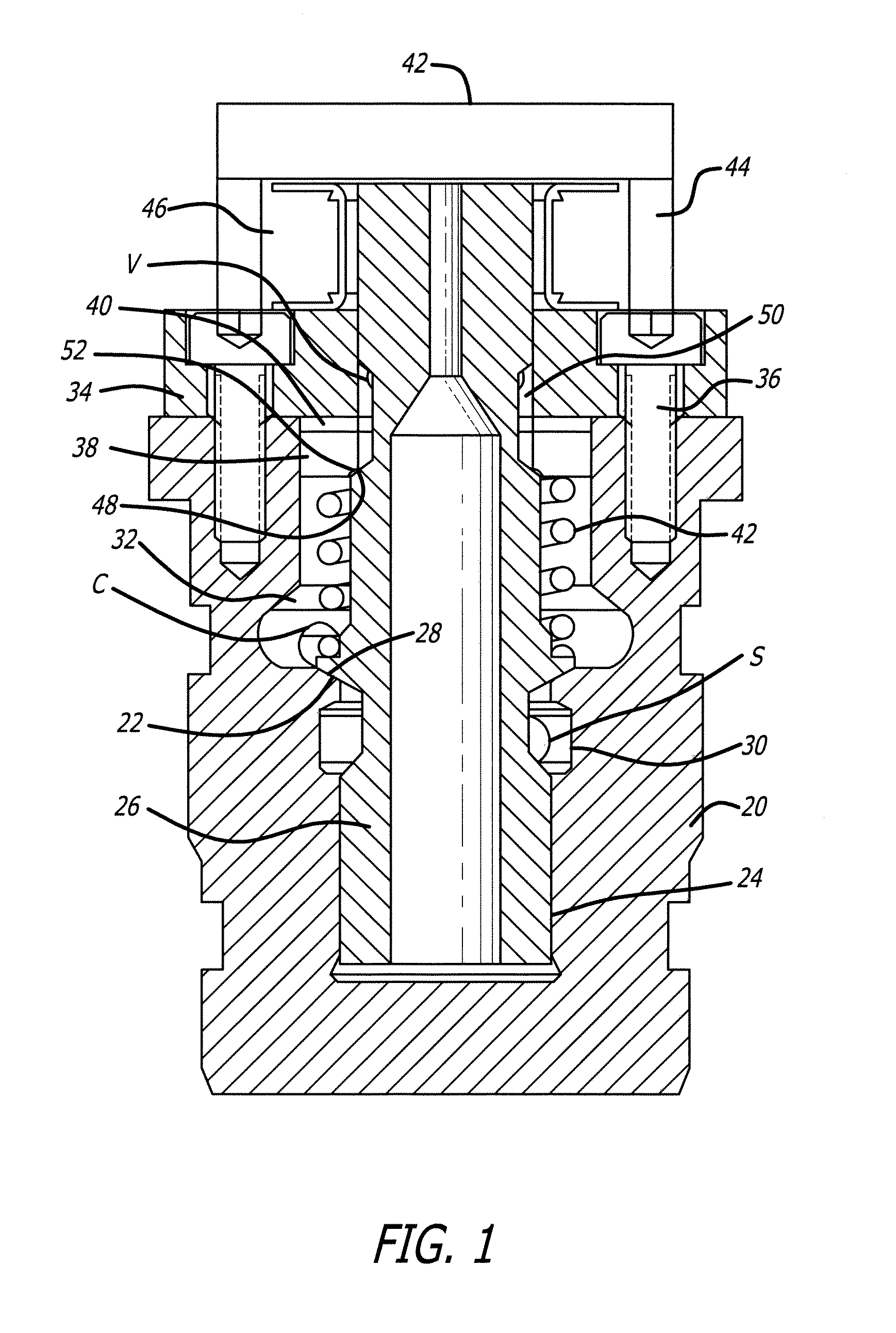
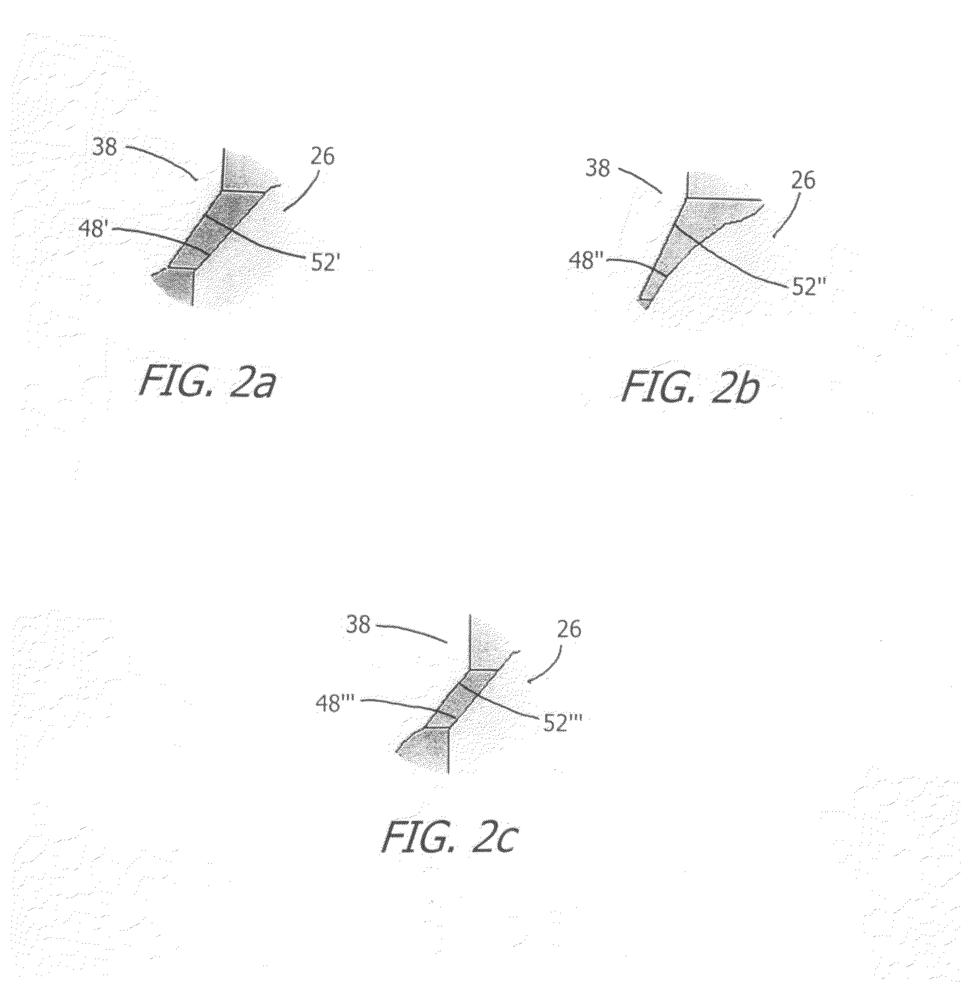
[0014]The object of the preferred embodiments of the present invention is to have a high pressure (for fuel) three-way valve with low leakage, good pressure balance (for minimal force requirements) and practical manufacturing. Accordingly the present invention comprises a three-way poppet valve that achieves hydraulic pressure balance in either the open or closed position. In order to achieve this, the poppet seat that is not part of (or located on) the main guide must be perfectly concentric with the main guide. If this is not achieved, the valve seat will not properly seat on the misaligned seat and will either not seal, or stick, or both. While this can easily be drawn or designed, it is not practical to manufacture. The present invention uses a floating seat that is easily manufactured and does not need to be perfectly concentric with the valve guide. Instead, the seat is allowed to “float” to find the optimum location, resulting in excellent sealing and minimal stiction. The required force is minimal, which is also key in minimizing the size of the actuator (such as a magnetic armature), further improving performance and packaging practicality.

Problems solved by technology

They provide acceptable but not superior controllability with relatively low cost.
On the other hand, needle control with three-way valves has not been commercialized to the same extent.
Three-way control valves provide superior flexibility in controlling the needle motion but are difficult to manufacture and / or to achieve pressure balance.
It is a very simple task to achieve pressure balance with a two-way valve but more difficult with a three-way valve.
It is also simple to achieve pressure balance with three-way valves if a spool valve is used, but a spool valve leaks excessively if used with fuel at elevated pressures as required for fuel injected engines.
However, the flexibility in controlling the needle motion during both opening and closing through the entire pressure range is not optimal, since there is no specific orifice to control the opening rate and closing rate independently, as is the case with a three-way valve.
However, none of the valves are able to achieve the pressure balance of the present invention.

Method used


Image

  • Three-way poppet valves with floating seat
  • Three-way poppet valves with floating seat
  • Three-way poppet valves with floating seat

Examples


Embodiment Construction

[0014]The object of the preferred embodiments of the present invention is to have a high pressure (for fuel) three-way valve with low leakage, good pressure balance (for minimal force requirements) and practical manufacturing. Accordingly the present invention comprises a three-way poppet valve that achieves hydraulic pressure balance in either the open or closed position. In order to achieve this, the poppet seat that is not part of (or located on) the main guide must be perfectly concentric with the main guide. If this is not achieved, the valve seat will not properly seat on the misaligned seat and will either not seal, or stick, or both. While this can easily be drawn or designed, it is not practical to manufacture. The present invention uses a floating seat that is easily manufactured and does not need to be perfectly concentric with the valve guide. Instead, the seat is allowed to “float” to find the optimum location, resulting in excellent sealing and minimal stiction. The re...


PUM


Abstract

Three-way poppet valves having a poppet valve body, first and second poppet valves disposed in a valve guide within the body for motion between first poppet valve open and first poppet valve closed positions, a first poppet valve seat disposed in the poppet valve body so as to have freedom in a plane perpendicular to the poppet valve axis, the first poppet valve, when moving to the closed position, engaging the first poppet valve seat and centering the first poppet valve seat with respect to the first poppet valve, and when in the closed position, holding the first poppet valve seat against the poppet valve body, and a second poppet valve connected with the first poppet valve, the poppet valve body having a second poppet valve seat, the second poppet valve being in the closed position when the first poppet valve is in the open position and being in the open position when the first poppet valve is in the closed position.

Description

CROSS-REFERENCE TO RELATED APPLICATION[0001]This application claims the benefit of U.S. Provisional Patent Application No. 60 / 779,621 filed Mar. 6, 2006.BACKGROUND OF THE INVENTION[0002]1. Field of the Invention[0003]The present invention relates to the field of three-way poppet valves.[0004]2. Prior Art[0005]An object of the preferred embodiment of the present invention is to have a high pressure (for fuel) three-way valve with low leakage, good pressure balance (for minimal force requirements) and practical manufacturing. While the valve of the present invention has other uses, the preferred embodiment is intended for use in fuel injector for fuel injected engines, and the prior art will be discussed primarily with respect to such use.[0006]“Conventional” two-way needle control valves to control the motion of a diesel injector's needle valve have been in use for quite some years. They provide acceptable but not superior controllability with relatively low cost. On the other hand, ...

Claims


Application Information

Patent Timeline
Patent Type & Authority Patents(United States)
IPC IPC(8): F16K11/044F15B13/04
CPCF16K11/044Y10T137/86493Y10T137/86919Y10T137/86622Y10T137/86879
Inventor STRAUSS, RANDALL JAMESPENA, JAMES A.KISS, TIBORQUINLAN, JOHN MATHEW
Owner STURMAN INDS
Why Eureka
Eureka Blog
Learn More