
Aeroengine oil tank fire protection system

a technology for oil tanks and engines, applied in the direction of machines/engines, efficient propulsion technologies, mechanical devices, etc., can solve the problems of sight glass being particularly prone to failure, not being able to provide adequate cooling oil,

Inactive Publication Date: 2010-03-23
ROLLS ROYCE PLC
View PDF14 Cites 14 Cited by
  • Summary
  • Abstract
  • Description
  • Claims
  • Application Information

AI Technical Summary

Benefits of technology

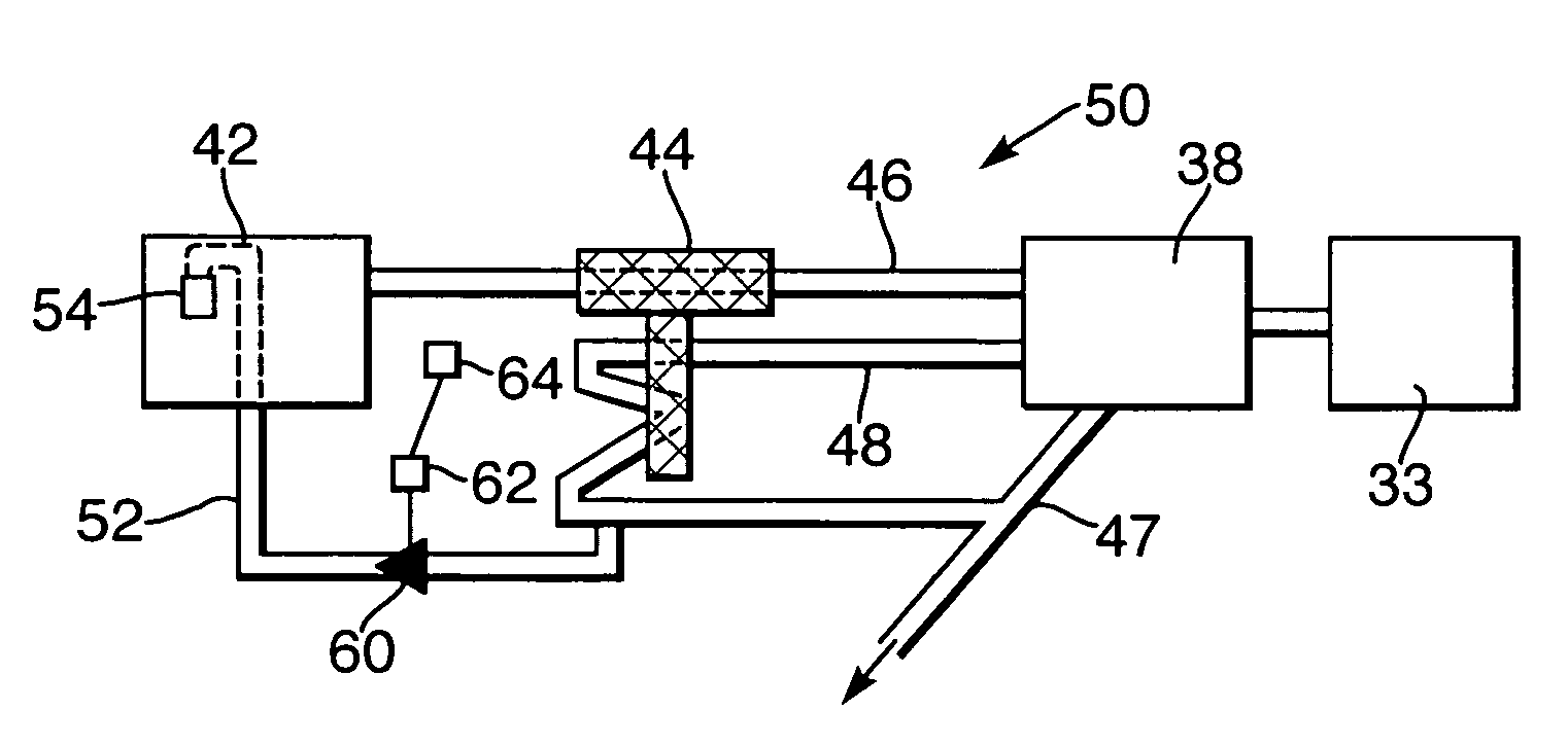
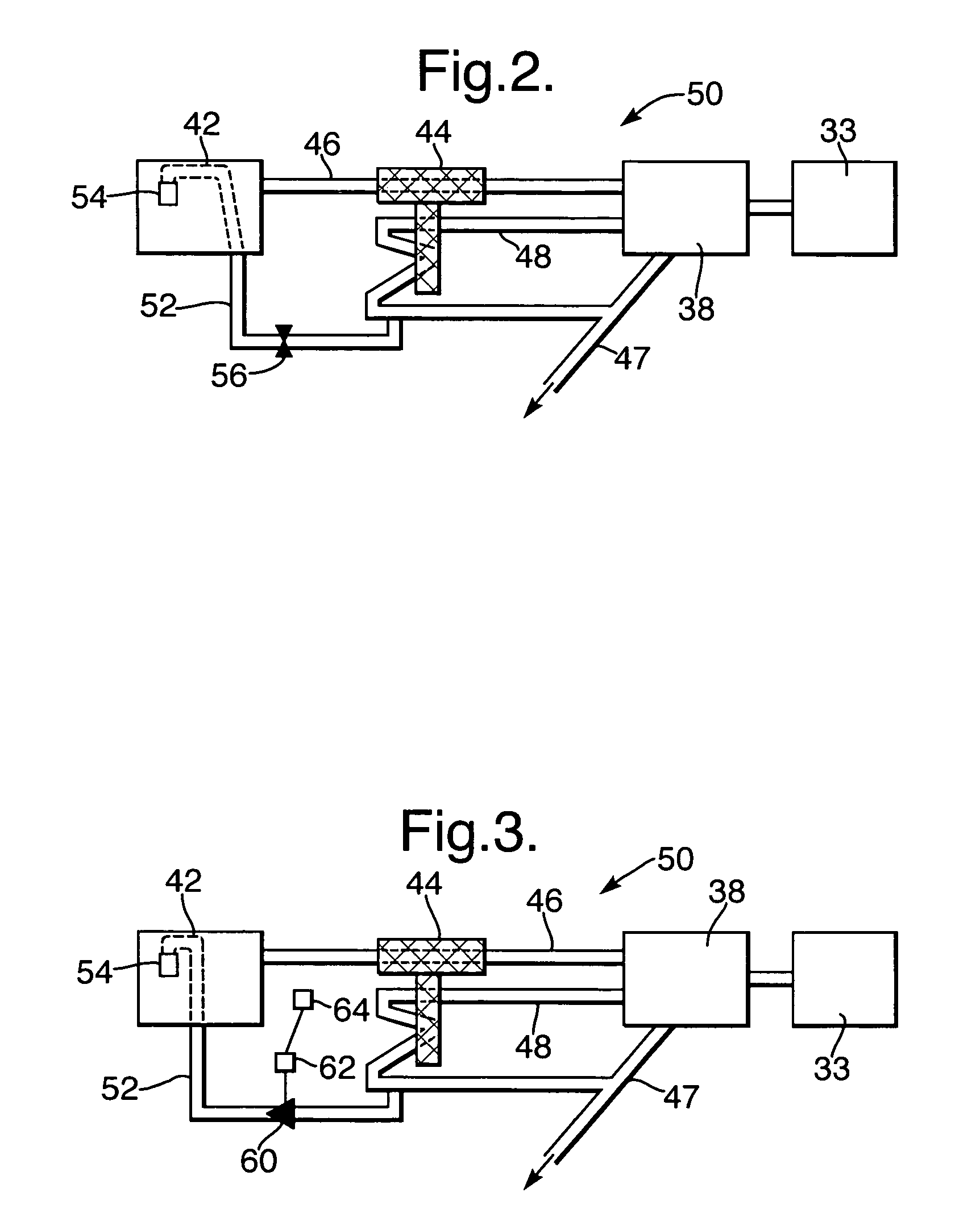
[0008]Preferably, the variable flow valve is operable via a sprung loaded valve, which is responsive to the oil pressure in the anti-siphon pipe, to increase oil flow therethrough at low engine speeds.
[0011]Preferably, the supply of oil provided to the sight glass in the tank is adequate to prevent failure of the sight glass through fire.

Problems solved by technology

However, this arrangement is not capable of providing adequate cooling oil for the sight glass to satisfy the minimum fire protection time required by the FAA and CAA.
This problem is particularly apparent as the cooling oil of the conventional arrangement is driven by means associated to the engine speed, thus where the engine is at low power the sight glass is particularly prone to failure through fire damage.

Method used


Image

  • Aeroengine oil tank fire protection system
  • Aeroengine oil tank fire protection system
  • Aeroengine oil tank fire protection system

Examples


Embodiment Construction

[0018]With reference to FIG. 1, a ducted fan gas turbine engine generally indicated at 10 has a principal and rotational axis 11. The engine 10 comprises, in axial flow series, an air intake 12, a propulsive fan 13, an intermediate pressure compressor 14, a high-pressure compressor 15, combustion equipment 16, a high-pressure turbine 17, and intermediate pressure turbine 18, a low-pressure turbine 19 and an exhaust nozzle 20. A nacelle 21 generally surrounds the engine 10 and defines both the intake 12 and the exhaust nozzle 20.

[0019]The gas turbine engine 10 works in the conventional manner so that air entering the intake 12 is accelerated by the fan 13 to produce two air flows: a first air flow into the intermediate pressure compressor 14 and a second air flow which passes through a bypass duct 22 to provide propulsive thrust. The intermediate pressure compressor 14 compresses the air flow directed into it before delivering that air to the high pressure compressor 15 where further...


PUM


Abstract

A gas turbine engine comprising an oil system and a gearbox, the gearbox is driven by at least one engine shaft, the oil system comprises a pump drivingly connected to the gearbox, an oil tank connected to the pump via a supply pipe and a delivery pipe connecting the pump to the engine for delivery of oil thereto, an anti-siphon pipe is connected between the tank and the delivery pipe to provide an excess oil flow to the engine characterized in that the anti-siphon pipe includes a variable flow valve for regulating the flow of oil passing therethrough such that at low engine speeds an adequate supply of oil is provided to a sight glass in the tank.

Description

FIELD OF THE INVENTION[0001]The present invention relates to an oil tank fire protection arrangement and a method of operating the same and in particular to providing such a system for a gas turbine engine.BACKGROUND OF THE INVENTION[0002]In a conventional gas turbine engine an oil system incorporates an anti-siphon pipe. This pipe returns part of the engine oil flow back to the tank (see FIG. 2). The function of the anti-siphon spill is to provide an excess of oil flow where the engine oil flows need adjusting. The anti-siphon pipe provides an air break in the system to avoid the oil draining to the lowest point in the system. Further, the anti-siphon pipe provides some cooling for a sight glass, used for monitoring the oil reserve, in the oil tank.[0003]However, this arrangement is not capable of providing adequate cooling oil for the sight glass to satisfy the minimum fire protection time required by the FAA and CAA. This problem is particularly apparent as the cooling oil of the...

Claims


Application Information

Patent Timeline
IPC IPC(8): F02C7/00F02C7/06F02G3/00F01D25/20F02C7/14F02C7/25F02C7/36
CPCF01D25/20F02C7/14F02C7/25F02C7/36Y02T50/675Y02T50/60
Inventor CHAMPION, CLARE DCHRISTOL, PHILIPPE
Owner ROLLS ROYCE PLC
Learn More