
Plasma display panel having honeycomb supporting structures

a technology of supporting structure and display panel, which is applied in the field of display panel, can solve the problems of reducing the breadth of the barrier rib, reducing not providing enough structural strength, so as to improve the yield factor of assembling the substrate, prevent cracking, peeling or bulging, and enhance the structural strength

Inactive Publication Date: 2010-03-09
CHUNGHWA PICTURE TUBES LTD
View PDF14 Cites 1 Cited by
  • Summary
  • Abstract
  • Description
  • Claims
  • Application Information

AI Technical Summary

Benefits of technology

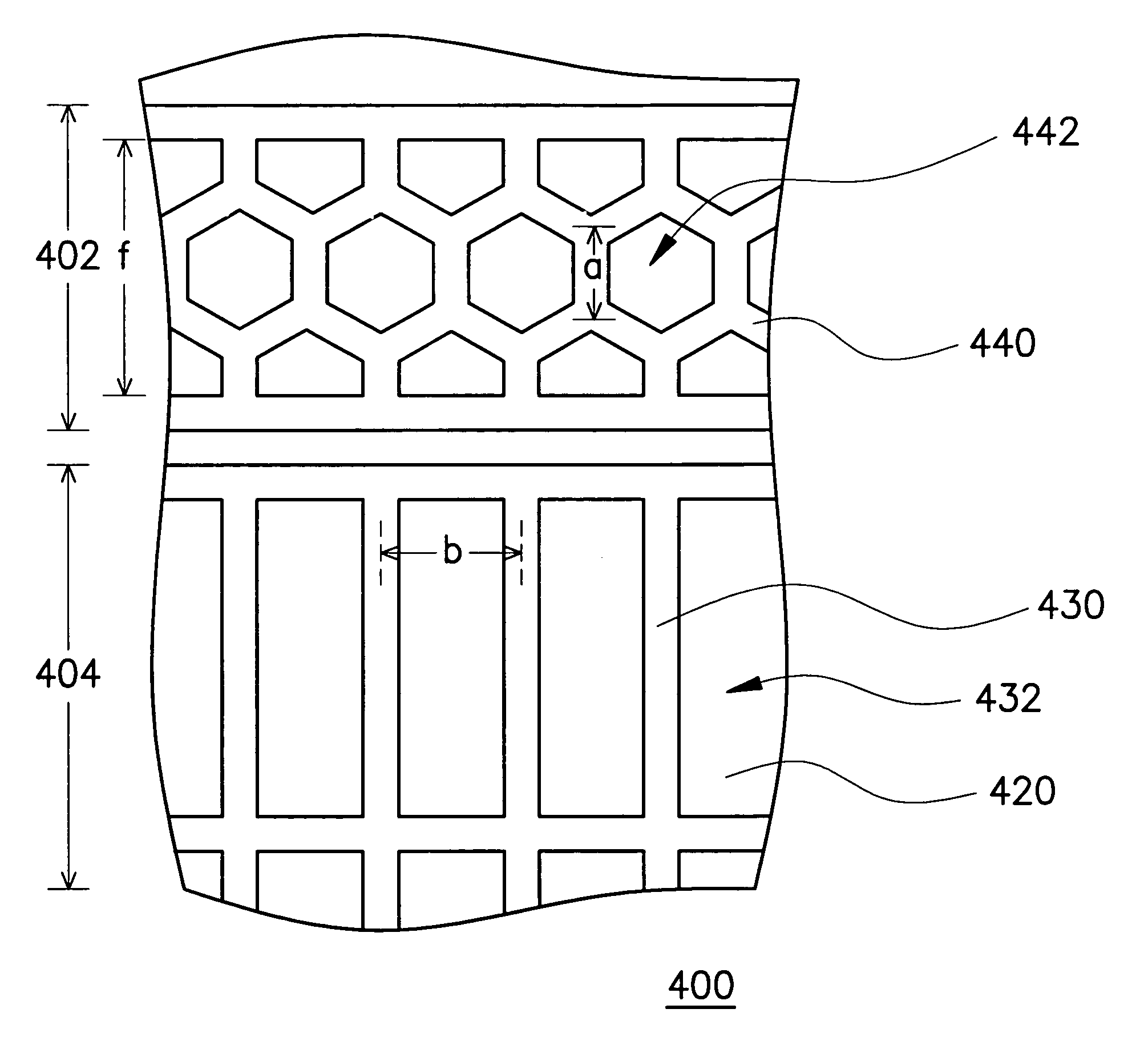
[0008]Accordingly, the present invention is directed to providing a plasma display panel and a manufacturing method of the barrier ribs thereof, which has honeycomb supporting structures in the non-display area to improve the yield factor of assembling the front substrate and the rear substrate as so to improve the display quality.
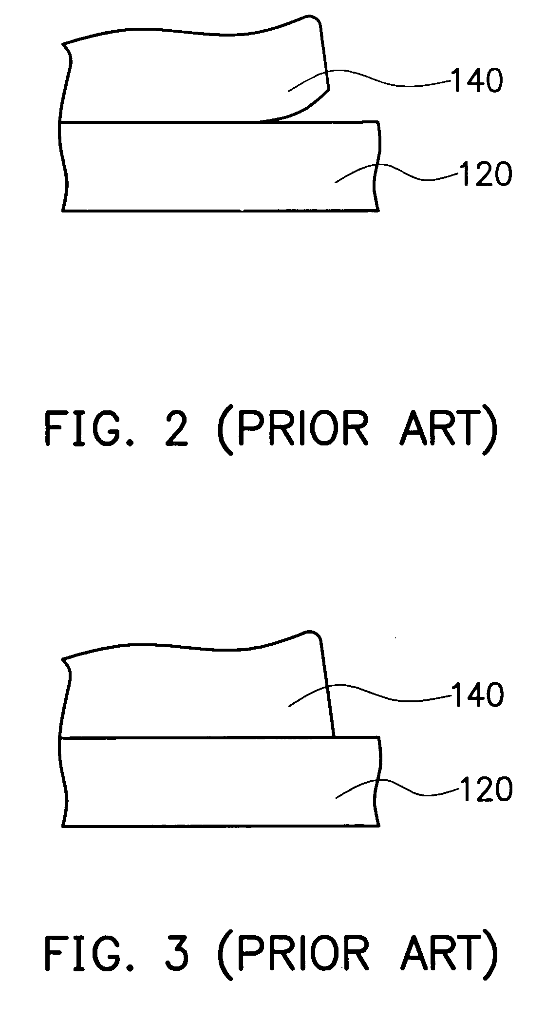
[0011]In conclusion, the plasma display panel and the manufacturing method of barrier ribs thereof in the present invention is directed to forming the honeycomb supporting structures in the non-display area while the discharging space is formed, wherein the honeycomb supporting structures can enhance the structural strength and prevent cracking, peeling, or bulging caused in conventional printing or sintering process so the yield factor of assembling the substrates can be improved.

Problems solved by technology

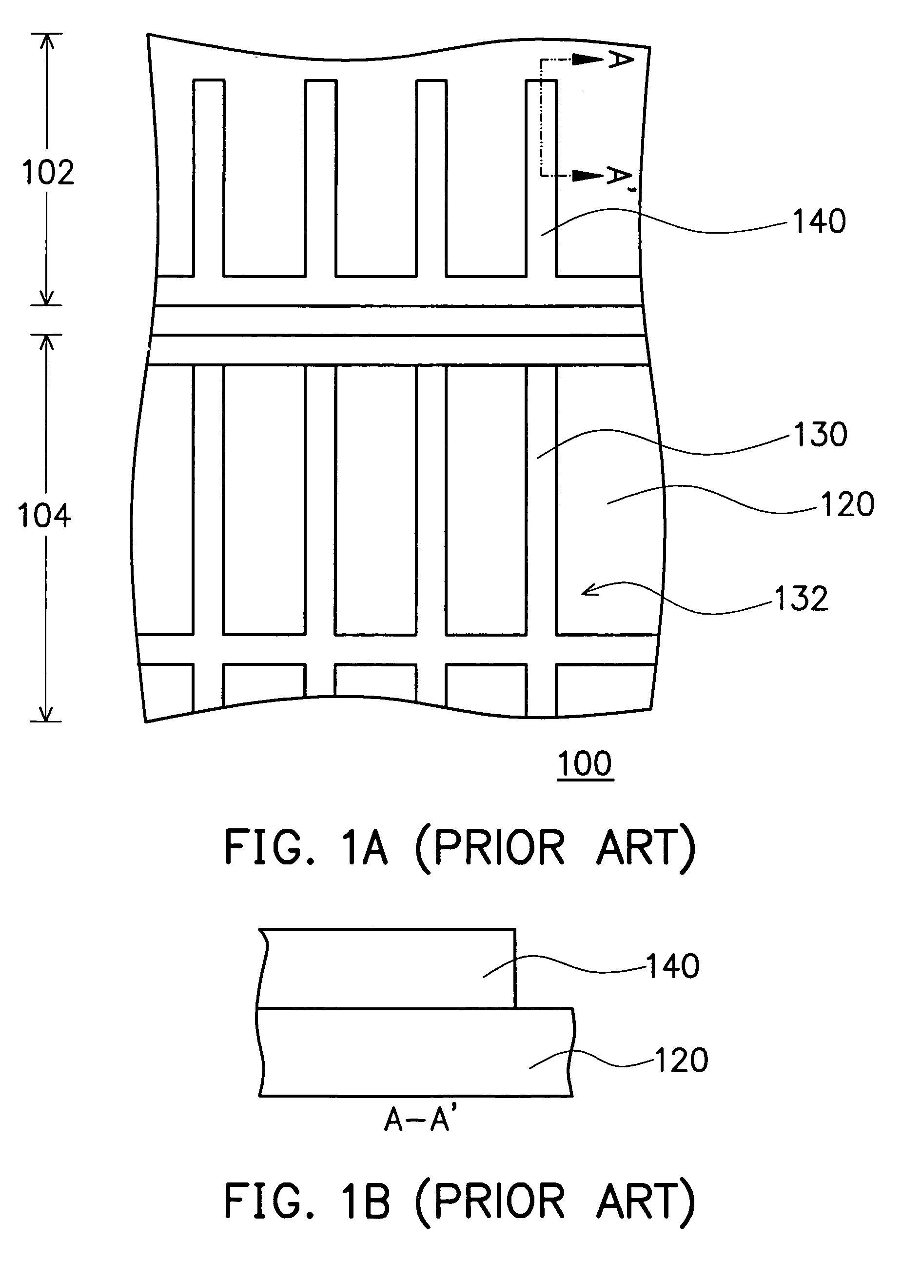
However, as modern display panels require higher resolution, the breadth of the barrier ribs has to be relatively decreased.
The narrowed stripe leads may not provide enough structural strength and can be damaged by the loading pressure in printing.
In either of the situation, the front substrate and the rear substrate will not be able to fit during assembly since the stripe leads are deformed, and will result in crosstalk disturbance during display so the display quality will be reduced.

Method used


Image

  • Plasma display panel having honeycomb supporting structures
  • Plasma display panel having honeycomb supporting structures
  • Plasma display panel having honeycomb supporting structures

Examples


Embodiment Construction

[0019]Reference will now be made in detail to the present preferred embodiments of the invention, examples of which are illustrated in the accompanying drawings. Wherever possible, the same reference numbers are used in the drawings and the description to refer to the same or like parts.

[0020]FIG. 4 is a partial perspective view of the plasma display panel in the present invention. As shown in FIG. 4, the plasma display 400 comprises a front substrate 410, a rear substrate 420, scan electrodes 412, sustain electrodes 414, address electrode 422, barrier ribs 430, and supporting ribs 440. The scan electrodes 412 and the sustain electrodes 414 are disposed in pairs in the front substrate 410 and are covered with a dielectric layer 416 and a passivation layer 418, which is made of MgO. In addition, the address electrodes 422, the barrier ribs 430, and the supporting ribs 440 are disposed in the rear substrate 420, wherein the barrier ribs 430, the front substrate 410 and the rear substr...


PUM


Abstract

A plasma display panel and a manufacturing method of barrier ribs thereof are provided. The plasma display panel is divided into a display area and a non-display area located in the periphery of the display area. When discharge space is formed in the display area by barrier ribs, a plurality of honeycomb supporting structures are formed in the non-display area at the same time. The honeycomb supporting structures can increase the yield factor of assembling the substrates, and then the display quality of the plasma display panels can be improved.

Description

BACKGROUND OF THE INVENTION[0001]1. Field of the Invention[0002]The present invention generally relates to a display panel and a manufacturing method thereof. More particularly, the present invention relates to a plasma display panel and a manufacturing method of barrier ribs thereof.[0003]2. Description of Related Art[0004]Flat panel displays serve as a communication interface between human and computers. At present, the flat panel displays include plasma displays, organic electro-luminescent displays (OELD) and liquid crystal displays (LCD). Among them, plasma displays have such advantages as big size, self-illuminance, wide-view angle, thinness and full color, and thus have the potential of becoming the mainstream flat panel display product in its next generation.[0005]In general, barrier ribs of a plasma display not only constitute discharging spaces in the display area of a panel, but also extend into the non-display area of the panel to assist the assembly of the front substra...

Claims


Application Information

Patent Timeline
Patent Type & Authority Patents(United States)
IPC IPC(8): H01J17/49
CPCH01J9/242H01J11/12H01J11/36H01J2211/365H01J2211/368
Inventor FU, CHUNG-LINCHIEN, YU-TINGCHIU, CHUN-CHIEN
Owner CHUNGHWA PICTURE TUBES LTD
Learn More