
Auxiliary power device for refrigerated trucks

a technology for auxiliary power devices and refrigerated trucks, which is applied in the direction of refrigerated goods vehicles, transportation and packaging, lighting and heating equipment, etc. it can solve the problems of releasing burning fuel, and being extremely inefficient, so as to reduce harmful emissions into the atmosphere, prevent overcurrent, and save fuel

Inactive Publication Date: 2010-03-09
PACY DAVID H
View PDF7 Cites 19 Cited by
  • Summary
  • Abstract
  • Description
  • Claims
  • Application Information

AI Technical Summary

Benefits of technology

[0017]It is another object to provide an auxiliary power device for refrigerated trucks that reduces the collective millions of hours of needless idling of engines, thereby saving fuel and reducing harmful emissions into the atmosphere.
[0018]It is still another object to provide an auxiliary power device for refrigerated trucks that prolongs engine life by reducing wear and tear.
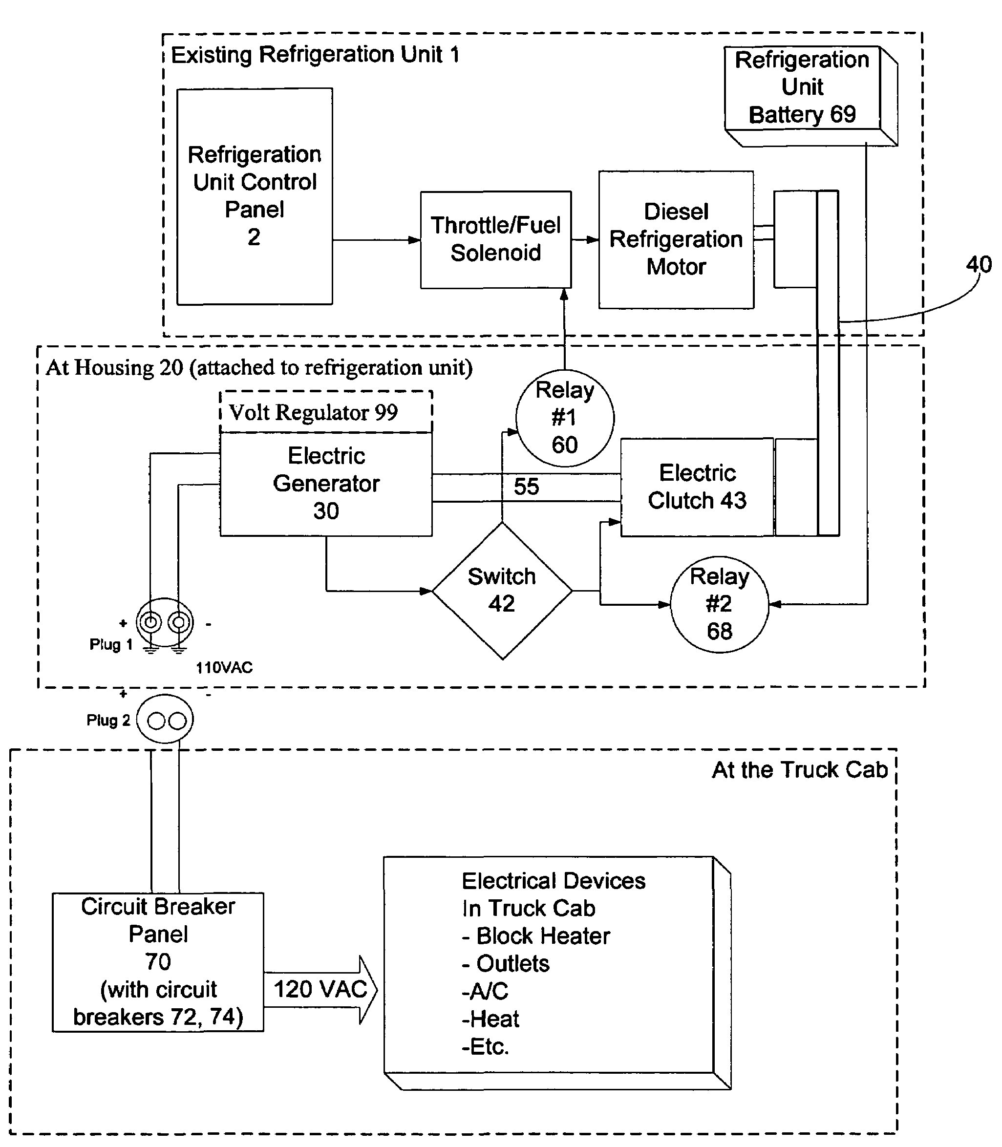
[0022]One approach is to regulate the generator power output mechanically by an optional electric clutch assembly on the generator to selectively engage the pulley assembly to start the generator drive. This affords a brief start-up delay during which two relays activate, one to control the motor speed of the refrigeration unit, and the other to prevent drainage of the refrigeration unit battery. A switch on the housing of the auxiliary power device is connected to the first relay, which is in turn connected to the existing fuel solenoid at the control panel of the refrigeration unit for controlling the speed of the diesel motor in the refrigeration unit upon engagement of the switch. When the switch is engaged the diesel motor speed is regulated (to a low speed of approximately 1400 rpm), and the pulley / electric clutch assembly is engaged to turn the generator and generate power at an acceptable 110V 60 Hz AC. The switch also controls a second relay that prevents drainage from the refrigeration unit battery when the generator is not generating power (albeit the present system does not charge the refrigeration unit battery). In operation, a driver simply turns the existing refrigeration unit on, switches on the generator via the switch to engage the pulley / electric clutch assembly and activate the first relay (controlling the motor speed of the refrigeration unit), thereby causing the pulley / electric clutch assembly to turn the electric generator and produce electric current for use in the cab.
[0024]In both of the foregoing cases the generator power is routed to the truck cab through a power distribution which includes a fused circuit breaker panel (with circuit breakers) mounted in the cab of the truck for distributing power from the electric generator into the truck cab, and yet preventing over-current thereto. Thus, the drive can power electric devices in the cab from the auxiliary power generation device without idling the truck's main engine. This reduces the collective millions of hours of needless idling of truck engines, thereby saving fuel, reducing harmful emissions into the atmosphere, and prolonging engine life by reducing wear and tear.

Problems solved by technology

Trucks across the country spend millions of hours parked, yet idling their engines, burning fuel and releasing harmful emissions into the atmosphere.
This is extremely inefficient and market forces are increasingly weighted against this:Diesel fuel prices are at an all time high ($2.60-3.60 per gallon)The government is passing increasingly strict idling and emissions laws.More and more energy-consuming amenities are being added to trucks to help the trucking industry find and retain quality drivers to man their fleets (they purchase optional creature comforts to enhance the driving experience).
Neither of the foregoing systems nor any other deliver any power to the cab.

Method used


Image

  • Auxiliary power device for refrigerated trucks
  • Auxiliary power device for refrigerated trucks
  • Auxiliary power device for refrigerated trucks

Examples


Embodiment Construction

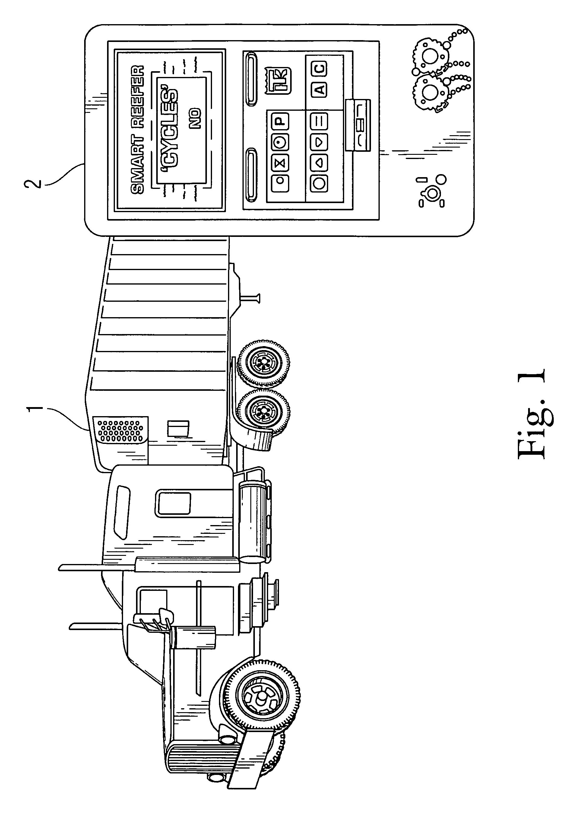
[0032]The present invention is an auxiliary power device for refrigerated trucks that acts as a power source to the truck's cab when the truck is parked, thereby allowing operation of heaters, air conditioning, outlets, engine block heaters, battery chargers, etc., all without idling the truck's engine. The auxiliary power device may be provided as original equipment in new refrigerated trucks, or may be a retrofit kit for existing trucks. A retrofit example is described in detail below implemented in conjunction with a conventional Thermoking® Smart Reefer diesel generator-powered refrigeration unit 1 at the front of the trailer, though most any diesel or hybrid diesel-electric refrigeration unit driven by a motor will suffice.

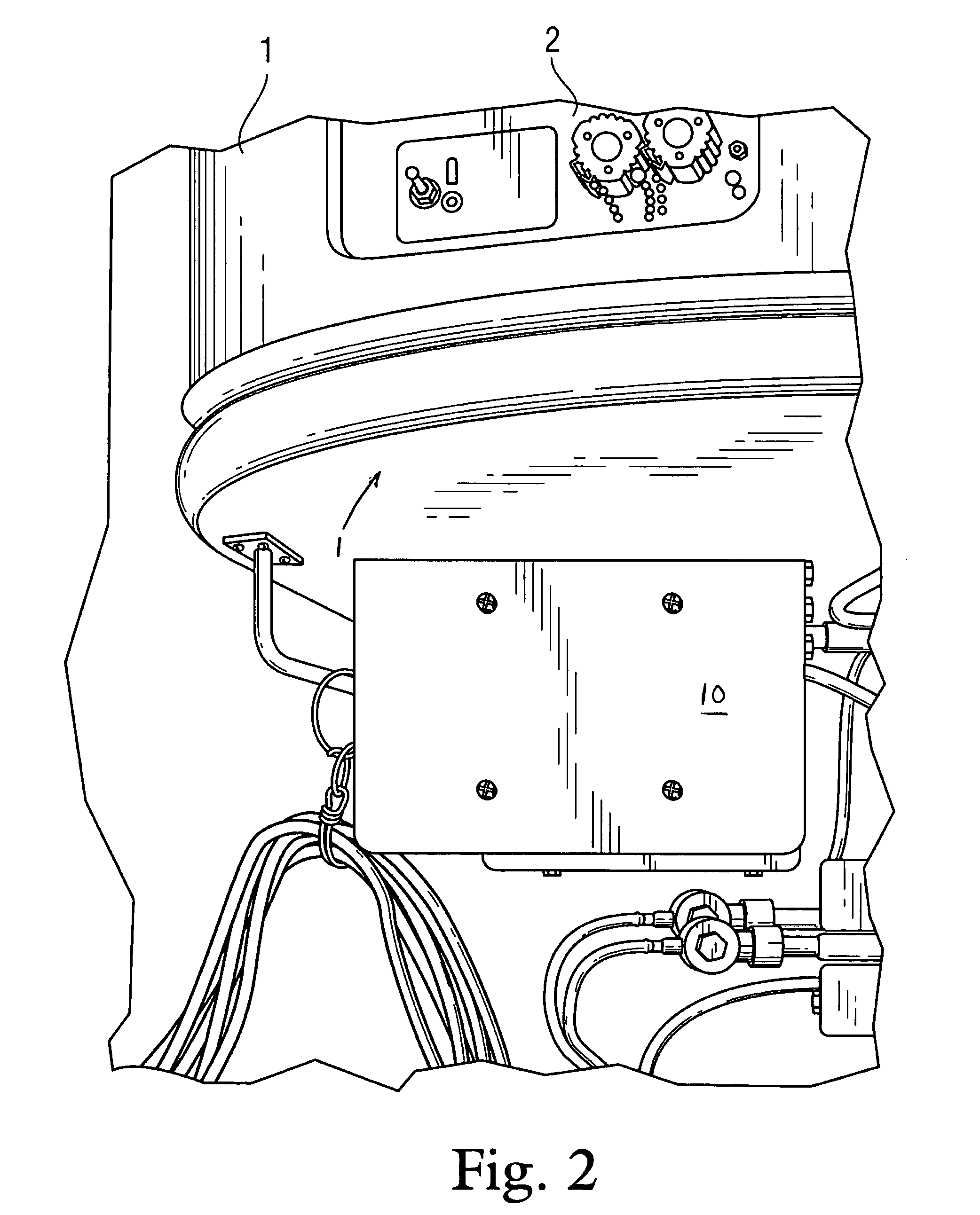
[0033]FIG. 2 is a side perspective view of the auxiliary power device 10 according to a preferred embodiment of the present invention implemented with a Thermoking® Smart Reefer diesel generator-powered refrigeration unit 1 at the front of the trailer. FIG. 3...


PUM


Abstract

An auxiliary power device for attachment to an existing refrigeration unit of a refrigerated trailer to serve as a power source to a truck cab, thereby allow operation of electrical devices in said cab without idling of the truck's engine. The auxiliary power device comprises a housing attached beneath the existing refrigeration unit, an electric generator enclosed within the housing, and a pulley assembly mounted in the housing and connected by drive shaft to the generator. The pulley assembly is connected via drive belt to the diesel motor in the existing refrigeration unit. When the generator is activated a first relay governs the speed of the diesel motor in the refrigeration unit, which turns the generator to generate power, and a second relay prevents drainage of the refrigeration unit battery. The power from the generator is routed through a breaker panel mounted in the cab of the truck for distributing and regulating power from the battery and / or generator into the truck cab. Thus, the driver can power electric devices in the cab from the auxiliary power generation device without idling the truck's main engine, thereby reducing fuel consumption, harmful emissions, and prolonging engine life.

Description

CROSS-REFERENCE TO RELATED APPLICATIONS[0001]The present application derives priority from U.S. Provisional Application Ser. No. 60 / 712,988; Filed: Aug. 31, 2005.BACKGROUND OF THE INVENTION[0002]1. Field of the invention[0003]The present invention relates to refrigerated trucks and trailers (“reefers”) and, more particularly, to an auxiliary power device for refrigerated trailers that acts as a power source to the truck's cab when the truck is parked, thereby allowing operation of heaters, air conditioning, outlets (for TV, microwaves, etc.), engine block heaters, and battery chargers, all without idling the truck's engine.[0004]2. Description of the Background[0005]When truck drivers park their tractor-trailers to load or unload, sleep, eat, shower or catch up on paperwork, most of the time they leave their truck running to keep the engine block warm and to operate the cab's air conditioning, heat, TV, VCR, computer and / or microwave. Trucks across the country spend millions of hour...

Claims


Application Information

Patent Timeline
Patent Type & Authority Patents(United States)
IPC IPC(8): F25B27/00
CPCB60H1/00014B60H1/00428B60P3/20Y02T10/88
Inventor PACY, DAVID H.
Owner PACY DAVID H
Learn More