
Internal combustion engine having a turbocharger having variable turbine geometry

a technology of variable turbine geometry and internal combustion engine, which is applied in the direction of machines/engines, liquid fuel engines, mechanical equipment, etc., can solve the problems of increasing construction costs, space requirements, and small energy potential, and achieve the effect of avoiding overtaxing the engine and small cos

Inactive Publication Date: 2002-06-04
DAIMLER AG
View PDF18 Cites 48 Cited by
  • Summary
  • Abstract
  • Description
  • Claims
  • Application Information

AI Technical Summary

Benefits of technology

The invention is a supercharged internal combustion engine having variable turbine geometry in such a manner that, using simple means and at small cost, an exhaust-gas recirculation system can be realized that avoids overtaxing the engine in extreme operating ranges.
In accordance with a second inventive embodiment, an exhaust-gas intercooler is disposed in the recirculation line of the exhaust-gas recirculation system. Charge air is used as a coolant in the exhaust-gas intercooler. In this way, when turbochargers having variable turbine geometries are employed, it is possible to use the excess air flowing in the intake line for cooling the hot, re-circulated exhaust gas. The boost pressure of the engine is thus limited, as a result of which it is assured that peak pressure limits are not exceeded, above which damage can occur to the engine. The heat removed from the charge air in the coolant circuit can be expelled into the surrounding atmosphere. In contrast to conventional exhaust-gas recirculation water coolers, no heat dissipation via the cooling system of the engine is necessary, so that fuel is saved due to the smaller power requirements of fans and water pumps.

Problems solved by technology

It is disadvantageous that the exhaust gas extracted downstream of the turbine is already expanded, so that only a very small energy potential is still available for driving the smaller turbine of the supercharger employed for conveying the exhaust gas.
A further disadvantage lies in the cumbersome design of the device, encompassing two turbochargers, as a result of which construction costs, space requirements, and factory costs are increased.

Method used


Image

  • Internal combustion engine having a turbocharger having variable turbine geometry
  • Internal combustion engine having a turbocharger having variable turbine geometry
  • Internal combustion engine having a turbocharger having variable turbine geometry

Examples


Embodiment Construction

Internal combustion engine 1 depicted in FIG. 1, can be, for example, the internal combustion engine of a commercial vehicle. The engine has a turbocharger 2 having a turbine 3 in the exhaust-gas line 6 and a compressor 4 in the intake line 7. Compressor 4, which is driven via a shaft 5 by turbine 3, compresses the combustion air taken in at atmospheric pressure p.sub.1 to an increased pressure p.sub.2. The combustion air compressed in compressor 4 is cooled in a charge air intercooler 8 downstream of compressor 4 and, subsequently, is fed to intake pipe 9 of internal combustion engine 1 at boost pressure p.sub.2s, for distribution among cylinder intakes 10. Increased boost pressure P.sub.2s results in a rise in the engine power and performance.

The exhaust gas is diverted via cylinder outlet manifolds 11 into exhaust-gas line 6 and is fed to turbine 3 at exhaust-gas backpressure p.sub.3. Downstream of turbine 3, the expanded exhaust gas at pressure p.sub.4 is discharged into the atm...


PUM


Abstract

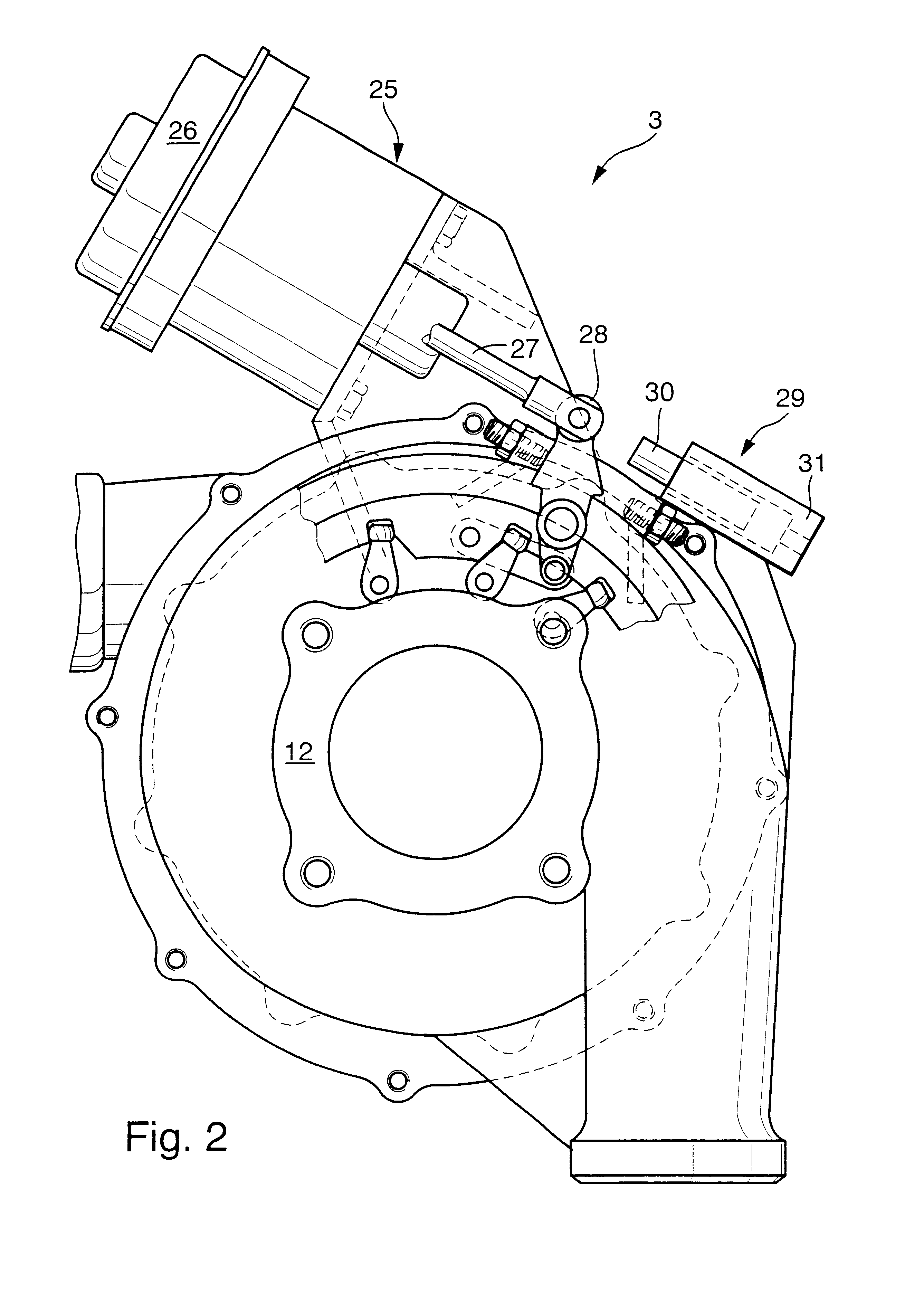
An internal combustion engine having a turbocharger with variable turbine geometry includes a compressor and an exhaust-gas turbine, whose turbine geometry can be adjusted to adjustably set the effective turbine cross section area. Using a closed-loop and open-loop control device, the operating state of the internal combustion engine can be detected, and the internal combustion engine can be adjusted as a function of the load and state. A movable limit stop is provided for limiting the control path of the variable turbine geometry, the limit stop being adjustable between a limiting position that limits the control path of the variable turbine geometry and a release position outside of the control path of the turbine geometry.

Description

The invention relates to an internal combustion engine having a turbocharger with variable turbine geometry.DESCRIPTION OF RELATED ARTIn supercharged diesel internal combustion engines used in commercial vehicles, it is known to furnish the turbines of the turbochargers with variable geometry to adjustably set the effective turbine cross section. In this way, it is possible to achieve desired levels of exhaust backpressure in the segment between the cylinders and the turbocharger, as a function of the operating state of the internal combustion engine. As a result of the variable geometry the power output of the turbine and the work done by the compressor can be adjusted as needed. A supercharged internal combustion engine having variable turbine geometry is known, for example, from German Patent Application 195 43 190 A1.To achieve an engine braking effect during braking operation of the internal combustion engine, the inlet guide baffle of the turbine is placed in a blocking positi...

Claims


Application Information

Patent Timeline
IPC IPC(8): F01D17/00F01D17/16F02D9/06F02B37/00F02M25/07F02B37/24F02B37/12F02D9/00F02B29/04F02B37/10F02B37/16F02M26/05F02M26/27
CPCF01D17/165F02B37/00F02B37/10F02B37/16F02B37/24F02M25/0707F02M25/073F02D9/06F02B29/0406F05D2220/40F02M25/0713Y02T10/121Y02T10/144F02M26/05F02M26/10F02M26/27Y02T10/12
Inventor GARTNER, UWE
Owner DAIMLER AG
Learn More