
Process for providing ethanol

a technology of ethanol and ethanol vapor, which is applied in the direction of oxygen compound purification/separation, azeotropic distillation, water/sewage treatment by ion exchange, etc., can solve the problem of contaminated water in the ethanol vapor used in regeneration

Active Publication Date: 2010-02-23
SUSTAINABLE TECH CORP
View PDF11 Cites 36 Cited by
  • Summary
  • Abstract
  • Description
  • Claims
  • Application Information

AI Technical Summary

Benefits of technology

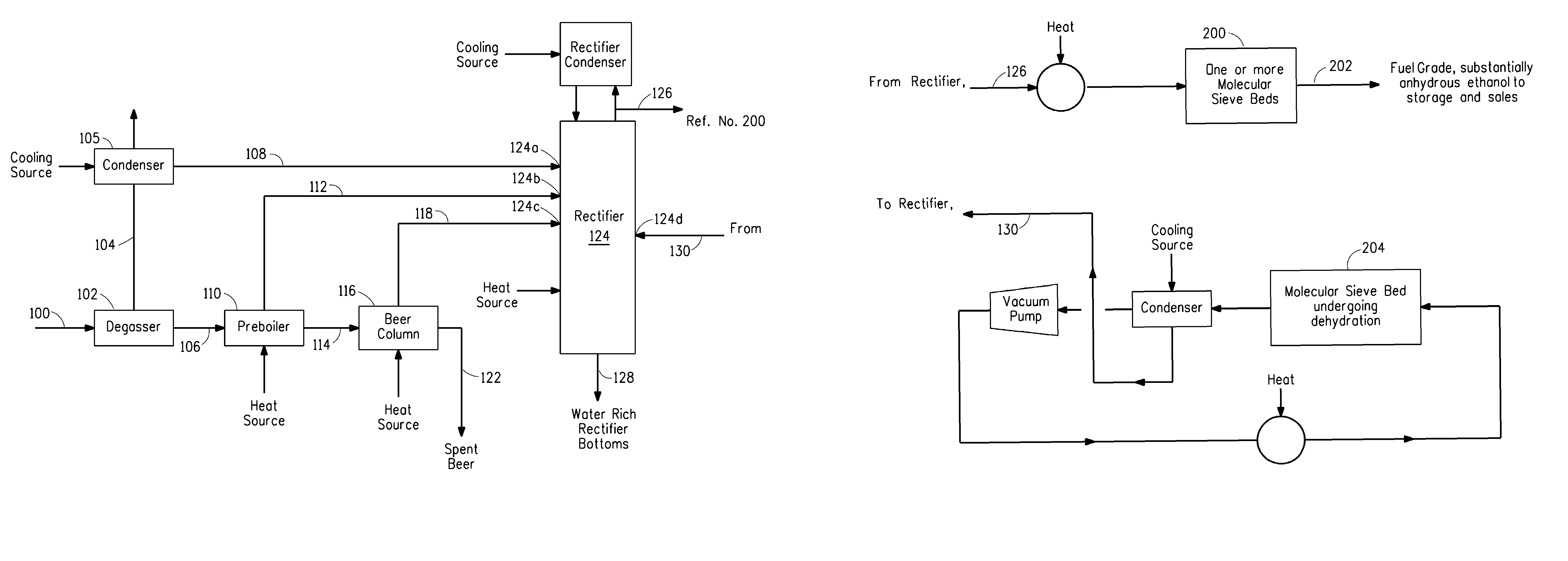
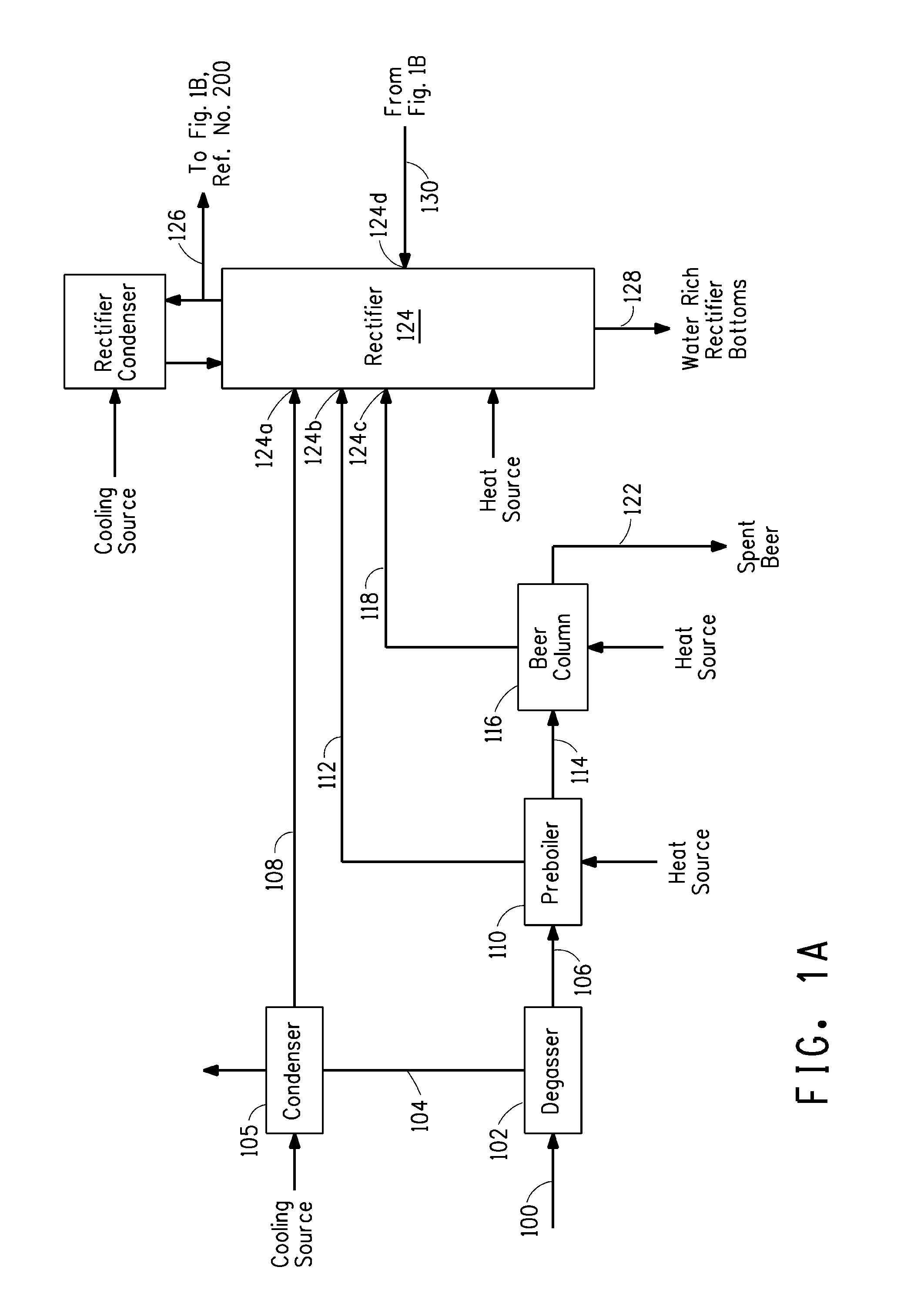
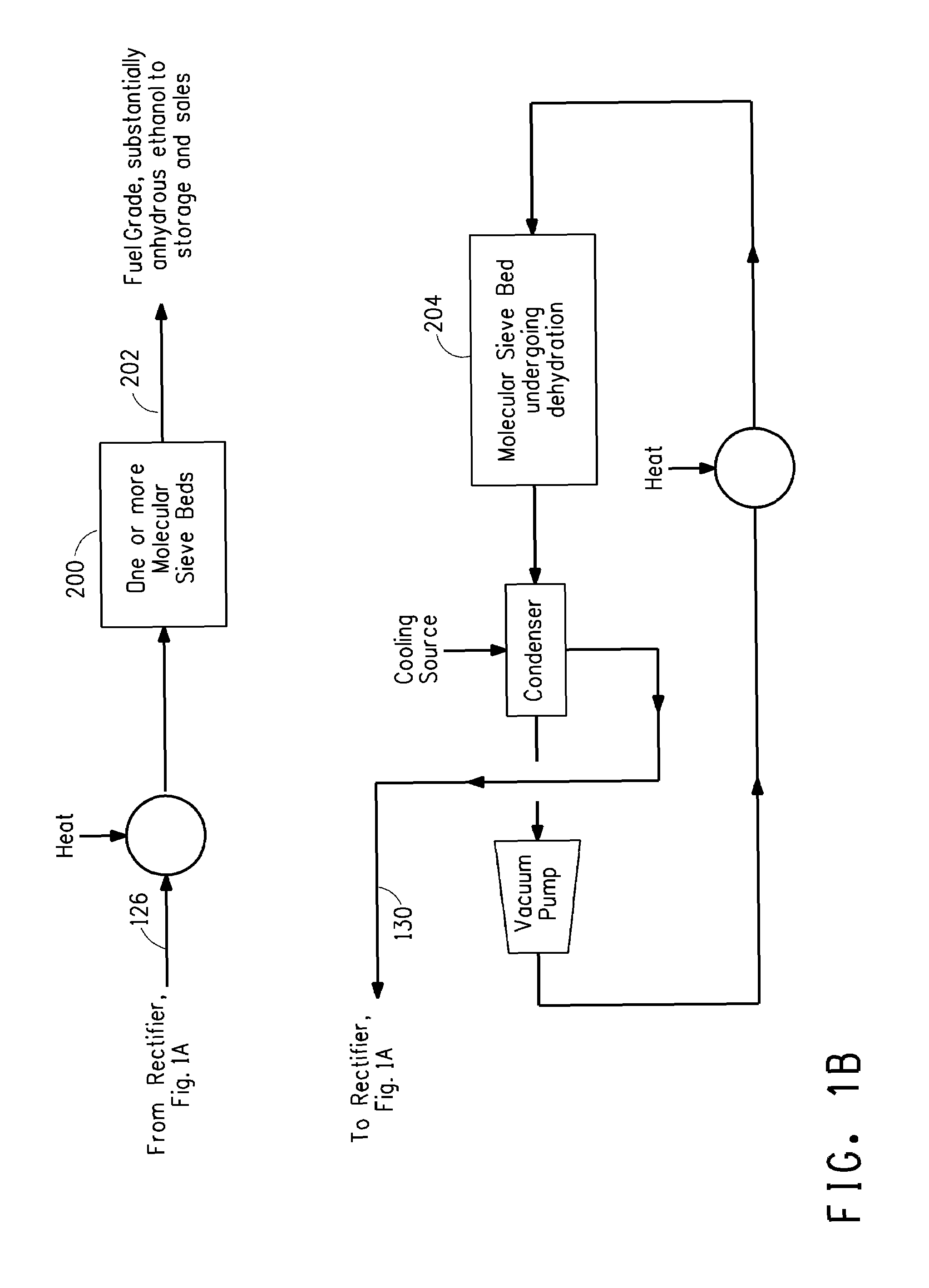
"The patent describes a process for making ethanol from beer. The process involves flashing carbon dioxide from the beer stream and boiling the beer feed to produce a vapor by-pass fraction and a beer column feed stream. The beer column feed stream is then distilled to produce an overhead vapor fraction and a spent beer fraction. The overhead vapor fraction and a water-rich rectifier bottoms stream are then combined to produce an ethanol-rich rectifier overhead vapor stream and a water-rich rectifier bottoms stream. The technical effect of this process is to provide a more efficient way to make ethanol from beer."

Problems solved by technology

This latter dehydration process has attracted much attention of scientists and engineers because it is a critical and expensive step in the refining process.
But a problem created by this approach is that the ethanol vapor used in regeneration is contaminated with water.
Increased capacity in the molecular sieve bed and / or rectifier would not eliminate the bottleneck of the beer column.

Method used


Image

  • Process for providing ethanol
  • Process for providing ethanol
  • Process for providing ethanol

Examples


example 1

[0049]In this Example, the degassed beer feed 106 is flashed in the pre-boiler 110 to provide a vapor by-pass fraction 112 of 4.75 wt % that is fed to the rectifier column 124 at second feed point 124b. Feed point 124b in this example corresponds to stage 9 of the 18 stages comprising the rectifier column. Further, the beer column is limiting and there is extra capacity in the upper section of the rectifier column. As shown in Table 6, overall capacity can be increased by 14.7%.

example 2

[0050]In this Example, the degassed beer feed 106 is flashed in the pre-boiler 110 to provide a vapor by-pass fraction 112 of 9.12 wt % that is fed to the rectifier column 124 at second feed point 124b. Feed point 124b in this example corresponds to stage 9 of the 18 stages comprising the rectifier column. Also, the beer column is limiting and there is sufficient extra capacity in the upper section of the rectifier column. As shown in Table 6, if the overall capacity can be increased by 25.7%.

example 3

[0051]In this Example, Example 1 is repeated, except that the vapor bypass fraction 112 of 4.75 wt % is partially condensed to provide a vapor by-pass condensate fraction of 40.6 wt % that is fed to the rectifier column 124 at fifth feed point 124e. Feed point 124e in this Example corresponds to stage 14 of the 18 stages comprising the rectifier column. The remaining vapor by-pass stream 304 is fed to the rectifier column 124 at sixth feed point 124f at stage 9. The beer column is the bottleneck in this Example. This combination of parameters results in an overall capacity increase of 14.7%. Capacity of the upper section of the rectifier column is also increased. If the upper section of the rectifier column is limiting, overall capacity is increased by 3.8%.


PUM

PropertyMeasurementUnit
wt %aaaaaaaaaa
wt %aaaaaaaaaa
energyaaaaaaaaaa

Abstract

The invention is a process for the purification of ethanol. In one embodiment the process includes boiling a degassed beer feed (106) in a pre-boiler (110) to provide a vapor by-pass fraction (112) that by-passes the conventional beer column and is fed into the rectifier column (124). The process allows free capacity in the rectifier column of new or established plants to be filled by ethanol-water vapor and / or condensate streams that do not originate from the beer column.

Description

STATEMENT OF GOVERNMENT RIGHTS[0001]This invention was made with support by the United States government and the government has certain rights in the invention.FIELD OF INVENTION[0002]The invention relates to processes for making motor fuel grade ethanol.BACKGROUND OF INVENTION[0003]Ethanol is an important source of energy and useful as an alternative to petroleum based gasoline and diesel products. Ethanol is produced by fermentation of a wide variety of organic feedstocks to provide a beer that is distilled and dehydrated to produce a high purity product. Aden, et al, in “Lignocellulosic Biomass to Ethanol Process Design and Economics Utilizing Co-Current Dilute Acid Prehydrolysis and Enzymatic Hydrolysis for Corn Stover”, NREL Report No. TP-510-32438; and Madson, P. W. and D. A. Monceaux, (Fuel Ethanol Production), in “Fuel Alcohol Textbook” Alltech Inc., 1999; provide an overview of the process. Substantial capital investment and energy are required to concentrate ethanol from a...

Claims


Application Information

Patent Timeline
Patent Type & Authority Patents(United States)
IPC IPC(8): B01D3/06B01D3/10B01D3/14C07C29/80C07C31/08
CPCB01D3/005B01D3/36C07C29/80C07C31/08
Inventor SYLVESTER, ROBERT G.BRESKE, STEPHEN THOMASCULVER, DAVID A.VRANA, BRUCE M.
Owner SUSTAINABLE TECH CORP
Learn More