Catheter flushing fluid lock system and method

a technology of flushing fluid and catheter, which is applied in the field of flushing fluid lock system, can solve the problems of inability to achieve the effect of reducing the effect of antimicrobial or anticoagulant, increasing the volume of the system, and enhancing the maintenance of the patency of the indwelling catheter

Inactive Publication Date: 2010-02-02
LYNN LAWRENCE ALLAN
View PDF7 Cites 7 Cited by
  • Summary
  • Abstract
  • Description
  • Claims
  • Application Information

AI Technical Summary

Problems solved by technology

The fluid lock system generally has a relatively fixed volume and limited elasticity so that variations in pressure within the flowing blood cannot cause substantial net or reciprocating flow of fluid between the locked system and the blood vessel.
However, despite its simplicity the lock procedure remains associated with considerable expense and substantial work for the nurses administrating and maintaining fluid lock systems.
In addition the lock procedure has, since its inception more than 15 years ago, been associated with an unacceptable failure rate, which contributes generally to the expense of the procedure.
Other than leakage, the most important modes of failures of a conventional lock system are either thrombotic, infectious, or a combination of both.
One of the factors precipitating failure is reflux of blood into the tip of the catheter lumen associated with an inadvertent internal volume reduction of the fluid lock.
As is standard with the lock procedure, these terminals generally automatically seal upon withdrawal of the cannula or luer after a flush maneuver, however, with many such systems, such withdrawal can result in removal of a small volume of fluid from the locked fluid column causing reflux of blood into the catheter lumen to accommodate that volume loss.
This process also induces migration of flush solution constituents from the lock, such as the anticoagulant or antimicrobial and this can contribute to failure.
However, some blood still slowly penetrates the lumen at the tip of these catheters.
Since, at the present time, most drug vials have elastomeric septae intended for receiving a sharp needle, this aspiration procedure often requires a disposable adapter to prevent needle sticks, which adds to the general cost of the lock procedure.
A simple saline flush also requires a sterile syringe and with some systems, a sterile cannula connected with the syringe, each further adding to the expense.
Because multi-dose vials carry the risk of cross contamination if not managed properly and because time dependent personnel costs are progressively rising in hospitals, an alternative, pre-filled disposable saline flush syringes are being offered by corporations.
However the storage of sterile flush solution within individually packaged syringes is also expensive, and such devices can cost in excess of $0.50 for a single unit.
There are hundreds of millions of such procedures performed in the US each year so that, considering all related costs, the expense of maintaining locks in the US alone probably exceeds several hundreds of millions of dollars.
In addition to the expense, each time the lock system is reentered the infection risk is increased to the patient because the outside instrument (such as a cannula, luer, or needle) can carry bacteria and yeast into the lock where they can proliferate and induce bacteremia and / or fungemia which are associated with considerable expense and can be fatal).
The catheter hub and internal lumen, have long posed an important infection risk problem for patients at home or in hospitals and the contamination risk is directly related to the number of entries into the system.
Considered collectively, throughout the United States, each year there are a vast number of such entries into lock systems for the purpose of flushing alone, for this reason, although the infectious risk of each flush maneuver is low, the number of patients who die each year due to a contamination during a routine flush, although difficult to measure, is probably quite high.
In addition, although each event is again associated with a low occupational risk, the nurse remains potentially exposed to infectious material, and potentially infectious waste is generated, anytime a disposable device such as a cannula enters a tubing system connected to a patient's vascular system.
Central catheters are exposed to substantially greater pressure variations, and are often left in for many weeks, and pose an increased risk in the event of lock entry related colonization.
Furthermore, the state of facilitated diffusion is heightened with these catheters and thrombus formation can readily occur, causing catheter occlusion and, at times, dangerous thrombus propagation.
However well formulated these new flush solutions are vulnerable to dilution as a function of facilitated diffusion within the lumen of the catheter adjacent the solution-blood interface.
This can cause a loss in efficacy if locked dwell times are extended between flushes.
However as can readily be seen by understanding the “kit” disclosed in the aforementioned patent, despite short-term efficacy, each of these newer locking procedures can require considerable effort and expense.
Many central catheters, especially multilumen catheters, have at least one lumen, which is idle for extended periods but which still requires frequent locking procedures unassociated with medication infusion.
In these patients flushing may represent the only access related infectious risk to the interior of the lock over a large percentage of the catheter dwell time.
The present inventor recognized that one important fundamental problem with conventional locked systems is that; the actions taken toward achieving the goal of prevention of infection and those toward the goal of prevention of thrombosis are potentially competitive.
In the case of a central catheter this residual flush solution can represent the expensive mixture of saline and an anticoagulant with or without an antimicrobial.

Method used


Image

  • Catheter flushing fluid lock system and method
  • Catheter flushing fluid lock system and method
  • Catheter flushing fluid lock system and method

Examples


Embodiment Construction

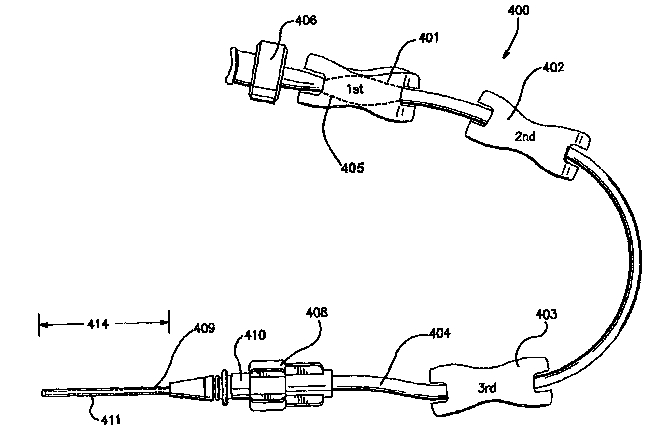
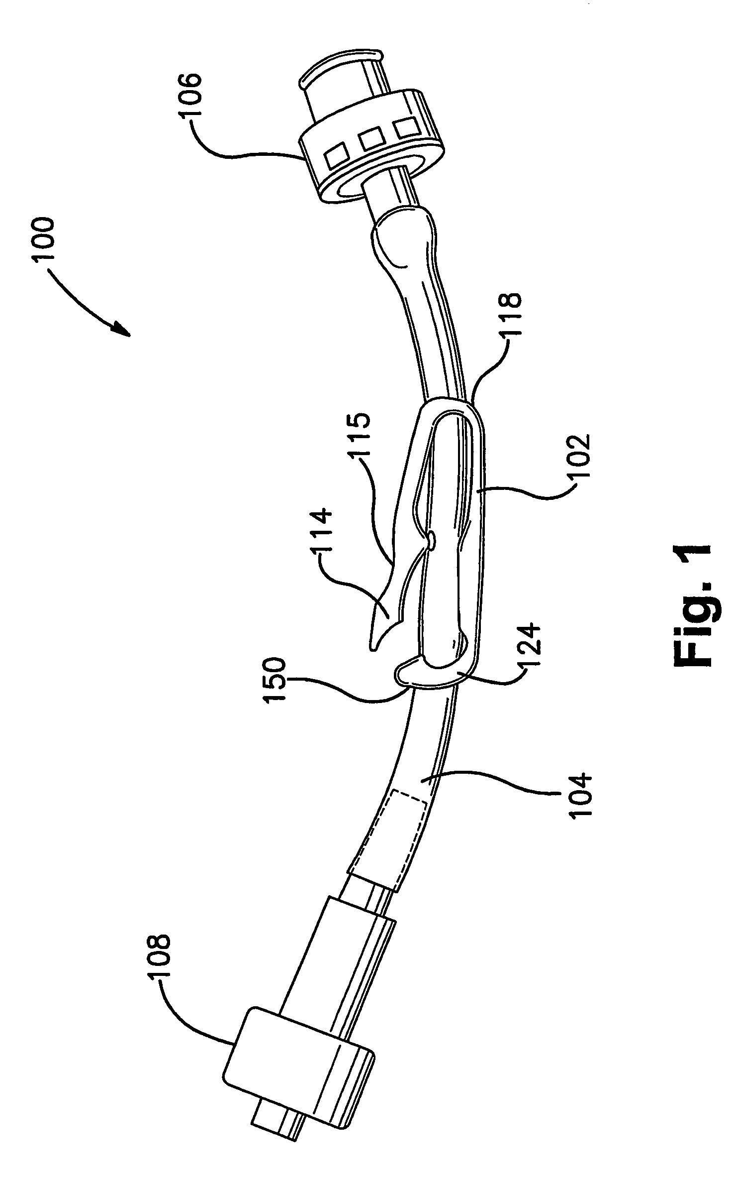
[0035]As shown in FIG. 1 a catheter flush generation system 100 includes a one piece, locking catheter-flushing clamp 102 (of the type disclosed in the aforementioned patent application of the present inventor) mounted upon an intravenous extension tube 104 having a closed proximal terminal 106, which as shown, is preferably a luer receiving valve integral with tubing 104 (as, for example, bonded and / or swayed onto tubing 104). Although a luer receiver is shown the proximal terminal 106 can be another closed hub such as an elastomeric hub for receiving a blunt cannula such as the hub marketed under the trade names Interlink and Lifeshield marketed by Baxter and Abbott Laboratories respectfully. The system 100 further includes a conventional distal luer lock connector 108 for engaging the hub of a catheter.

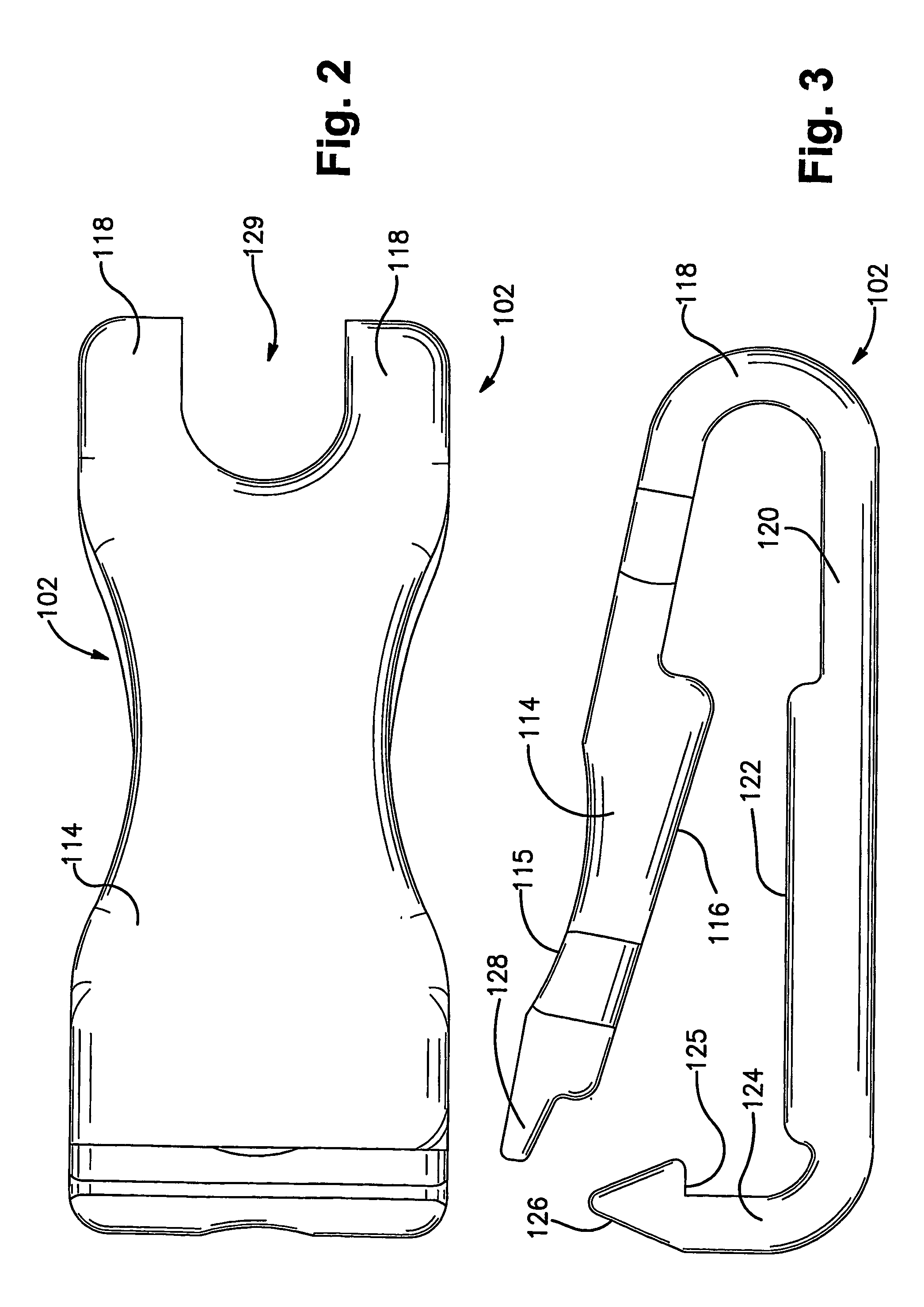
[0036]As shown in FIGS. 2-4, the catheter-flushing clamp 102 has a locking arm 114, with an top surface 115 for application of thumb pressure and an elongated, upper compression su...


PUM


Abstract

A catheter-flushing extension tube for maintaining the patency and sterility of the lumen of an indwelling catheter. The system is comprised of an extension tube in fluid connection with an indwelling catheter; the extension tube defines an internal volume and at least one sealed proximal terminal for intermittent connection with an external fluid source. The extension tube is configured such that the internal volume of the tube can be progressively reduced at a plurality of different times so that the extension tube itself provides the source of catheter flush solution for intermittently flushing the catheter.

Description

RELATED APPLICATIONS[0001]This application is a 371 application serial number PCT / US02 / 35163, filed Nov. 4, 2002.FIELD OF THE INVENTION[0002]This invention relates to fluid lock systems for indwelling catheters and to flushing procedures, solutions, and methods for maintaining the patency of fluid locked systems.BACKGROUND AND SUMMARY OF THE INVENTION[0003]Intravenous catheters represent the most common parenteral site for medication delivery. A large portion of these catheters, placed in either a peripheral or central vein, are left in situ for extended periods of time. Commonly these catheters are connected with tubing systems having closed sealed ends. These tubing systems are filled with a flush solution, which is injected through a seal or valve at a proximal terminal of the system. The act of injecting and filling with solution, a blind ended tube in fluid connection with a blood vessel has been termed a “lock procedure” because it sets up, in fluid connection with flowing blo...

Claims


Application Information

Patent Timeline
Patent Type & Authority Patents(United States)
IPC IPC(8): A61M31/00A61M5/14A61M39/22A61M39/28
CPCA61M39/225A61M39/284A61M2005/1403
Inventor LYNN, LAWRENCE ALLAN
Owner LYNN LAWRENCE ALLAN
Why Eureka
Try Eureka